
Intelligent LED lamp controller and control method

An LED lamp, an intelligent technology, applied in energy-saving control technology, lamp circuit layout, lighting devices, etc., can solve the problems of wasted labor, low efficiency, increased labor, etc., to ensure stability and maintainability, cost saving, shortening The effect of the construction period

Inactive Publication Date: 2011-01-12
杭州罗莱迪思科技股份有限公司
View PDF5 Cites 35 Cited by
  • Summary
  • Abstract
  • Description
  • Claims
  • Application Information

AI Technical Summary

Problems solved by technology

Disadvantages of this design: when the amount of lamps is large, the efficiency is low, the labor force increases, it is easy to confuse and install wrongly, and it is very inconvenient to maintain; 2) DIP mode: 8-bit electronic DIP switch is installed on the internal control board of the lamp produced by the lamp manufacturer , the program of the MCU is the same. After leaving the factory, the customer dials the corresponding address code according to the corresponding installation location.
However, most of the current LED lamps are installed outdoors, and the waterproof effect is required to be above IP67. The control parts are all inside the lamps. It is impossible to open the shells one by one to dial the switch and install the shells one by one. This is very efficient. Low, big limitations, waste too much labor
3) On-line single lamp address writing method. This design has a slight advantage over the previous two. The lamp stores the address code sent by the host computer (addresser) in the EEPROM that comes with the MCU. The address code is read in, and the working mode is: the lamps are all the same when they leave the factory. When the customer writes the address of the lamp before the lamp is installed, only one can be written at a time. After writing, install the lamp to the corresponding position, that is, Write a lamp address code and install one. If there is a problem with any lamp during operation and maintenance, it must be removed. After repairing, you must know the location of the lamp before you can write its address code. Relatively low and not easy to maintain

Method used


Image

  • Intelligent LED lamp controller and control method
  • Intelligent LED lamp controller and control method
  • Intelligent LED lamp controller and control method

Examples


Embodiment Construction

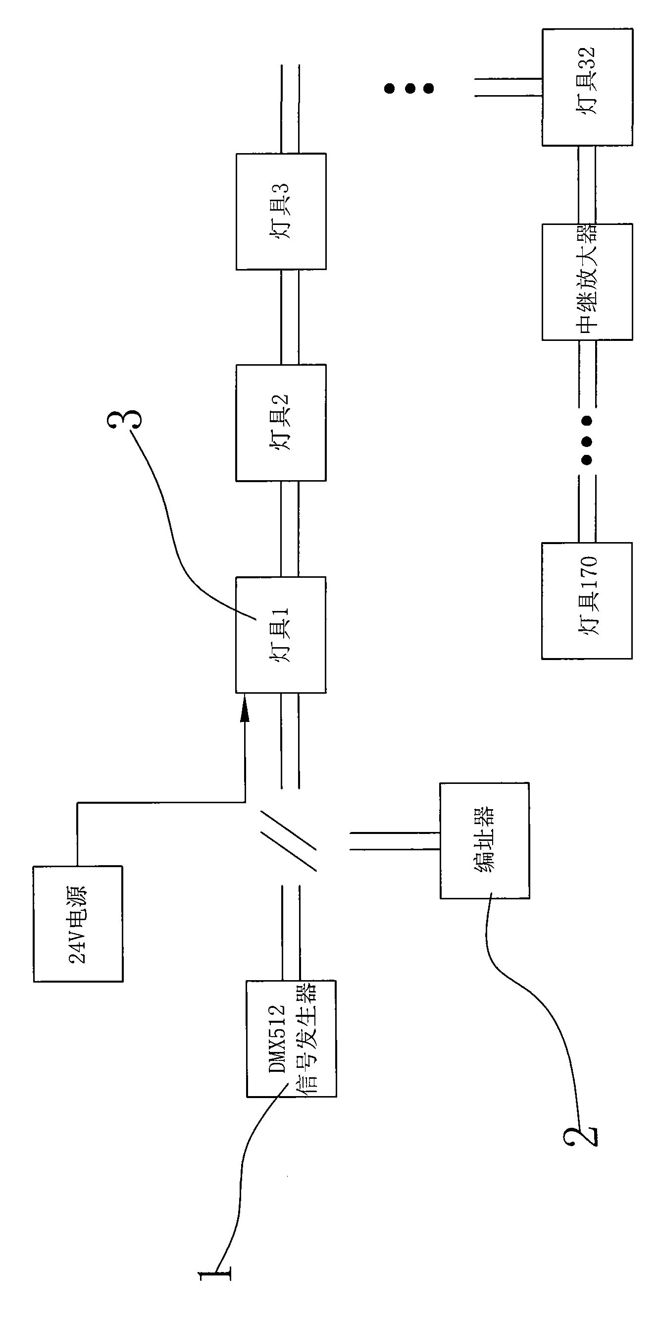
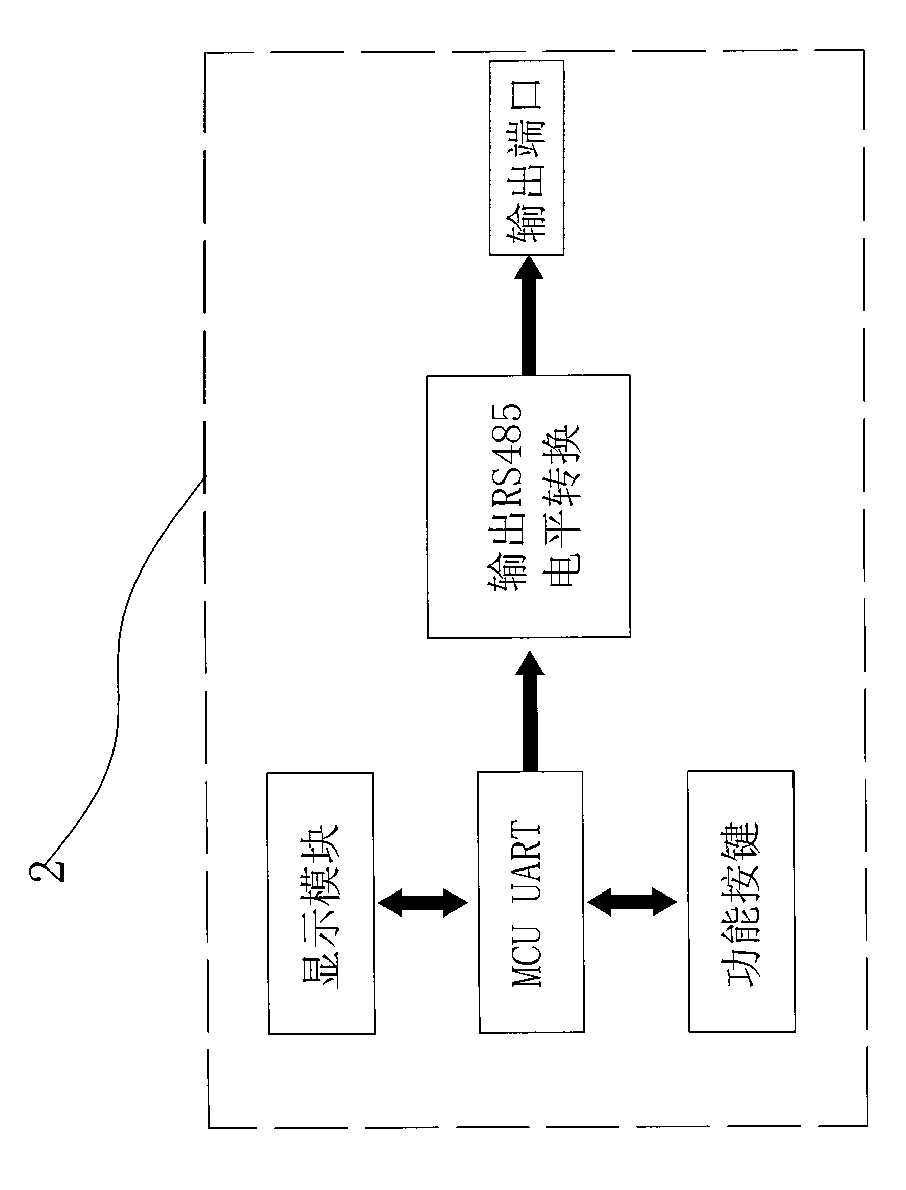
[0015] see figure 1 , including DMX512 signal generator (1), addresser (2) and lamps (3), by figure 1 It can be seen that the input RS485 bus and the output RS485 bus of all lamps are connected in parallel when the address code is not written and when the data sent by the DMX512 signal generator is normally received, that is, each lamp is connected through the input RS485 bus and the output RS485 bus. Connect in parallel with the DMX512 signal generator on the public RS485 bus for data communication. The DMX512 signal generator is responsible for sending standard DXM signals. The DMX512 signal generator can communicate with a host computer (PC) to form a LAN TCP / IP protocol communication. The upper computer is mainly responsible for configuring the working parameters of the DMX512 signal generator and monitoring the working status of the lamps (the principle of the DMX512 control system and the upper computer have been widely used in projects, so I will not introduce them in d...


PUM


Abstract

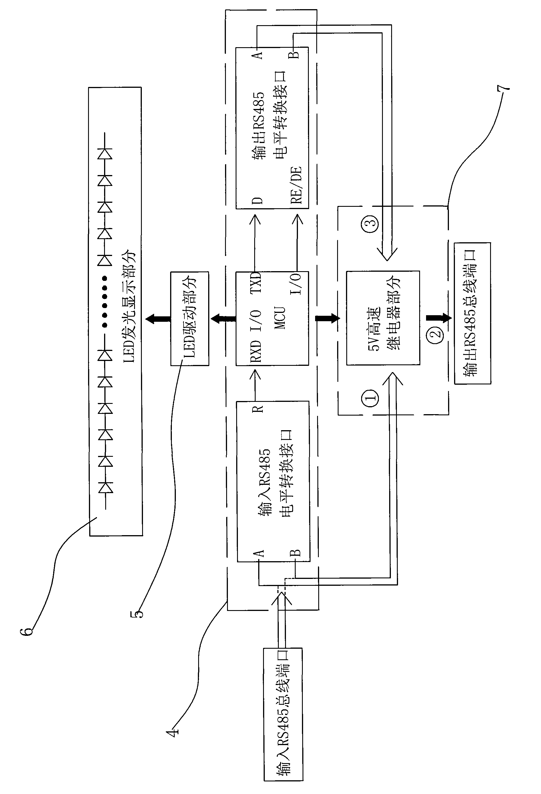
The invention relates to an intelligent LED lamp controller and a control method. The intelligent LED lamp controller is provided with a parallel connection / serial connection conversion unit which is connected with a decoding module. When all LED lamps are not subjected to address code writing and normally receive data transmitted by a DMX512 signal generator, the input RS485 bus and the output RS485 bus of the lamps are in parallel connection, namely the lamps are connected in parallel to a public RS485 bus through the input RS485 bus and the output RS485 bus to perform data communication with the DMX512 signal generator; and when an addressing device codes address codes for the lamps, the decoding module controls the parallel connection / serial connection conversion unit to change the parallel connection of the input and output RS485 buses in the lamps into serial connection. The intelligent LED lamp controller has the advantages that: the failure of one lamp cannot influence other lamps, and the assembly sequence and positions of the lamps can be changed freely, the lamps are serially connected during automatic addressing, and the lamps of the whole system are communicated in parallel through the buses once the address is coded.

Description

technical field [0001] The invention relates to the technical field of lamp control, in particular to an LED lamp controller based on the DMX512 protocol and a control method thereof. Background technique [0002] The address setting of the DMX512 decoding module of the traditional LED lamps is fixed at the factory, the on-site construction dial-up and the on-site external addresser are only set for a single set of lamps. The system is stable and the waterproof level is high, so the previous decoding module is unable to handle the address operation. After the luminaire is installed, no matter what luminaire needs to be energized and tested, especially for the LED luminaire that needs to be controlled, it needs to be debugged and edited to see if it meets the original design requirements. DMX512 is still the most used system in today's projects. . So how to debug the DMX512 system in the project? The lamps are the most numerous in the entire system, and each lamp is compos...

Claims


Application Information

Patent Timeline
IPC IPC(8): H05B37/02
CPCY02B20/42Y02B20/48Y02B20/40
Inventor 汪文龙黄武贤
Owner 杭州罗莱迪思科技股份有限公司
Learn More