Impact type vibration generator

A technology of vibrating generators and generators, which is applied to ocean energy power generation, engine components, machines/engines, etc. It can solve the problems of not being able to make full use of water flow energy, and achieve the effect of reducing maintenance costs

Inactive Publication Date: 2011-01-19
NANJING UNIV OF AERONAUTICS & ASTRONAUTICS
View PDF3 Cites 14 Cited by
  • Summary
  • Abstract
  • Description
  • Claims
  • Application Information

AI Technical Summary

Problems solved by technology

[0003] The purpose of the present invention is to overcome the deficiency that the current power generation method cannot make full use of the water flow energy in rivers, ditches and shallow seas, and provide a

Method used


Image

  • Impact type vibration generator
  • Impact type vibration generator
  • Impact type vibration generator

Examples


Embodiment 1

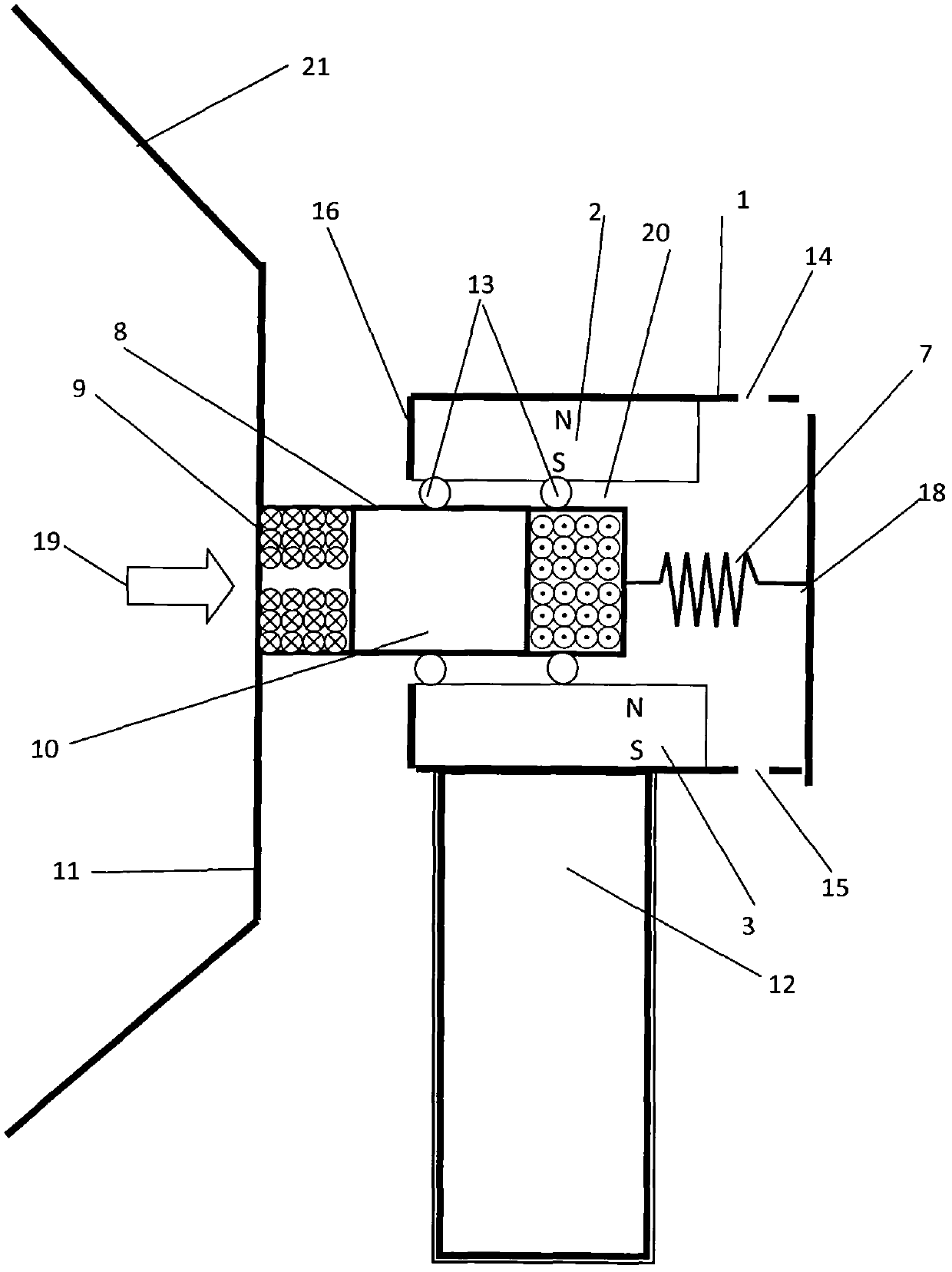
[0018] The vibration generator of embodiment 1 is as figure 1 shown.

[0019] The generator includes a generator frame 1, a first permanent magnet 2, a second permanent magnet 3, a coil box 8, a first spring 7, an excitation plate 11, and a smooth cylindrical support rod 13, wherein the first permanent magnet 2 is fixed on the box The top surface, the second permanent magnet 3 is fixed on the bottom surface of the casing. The opposite magnetic poles of the first permanent magnet 2 and the second permanent magnet 3 have different polarities. The surface of the permanent magnet is coated with anti-corrosion paint, and there is a gap 20 between the upper and lower permanent magnets. A part of the sealed coil box 8 is located in the gap, and the rest is located outside the gap. The coil box is provided with a closed cavity 10, and the excitation plate 11 is Fixed on the side of the coil box, one end of the first horizontal spring 7 is fixed on the other side of the coil box, the...

Embodiment 2

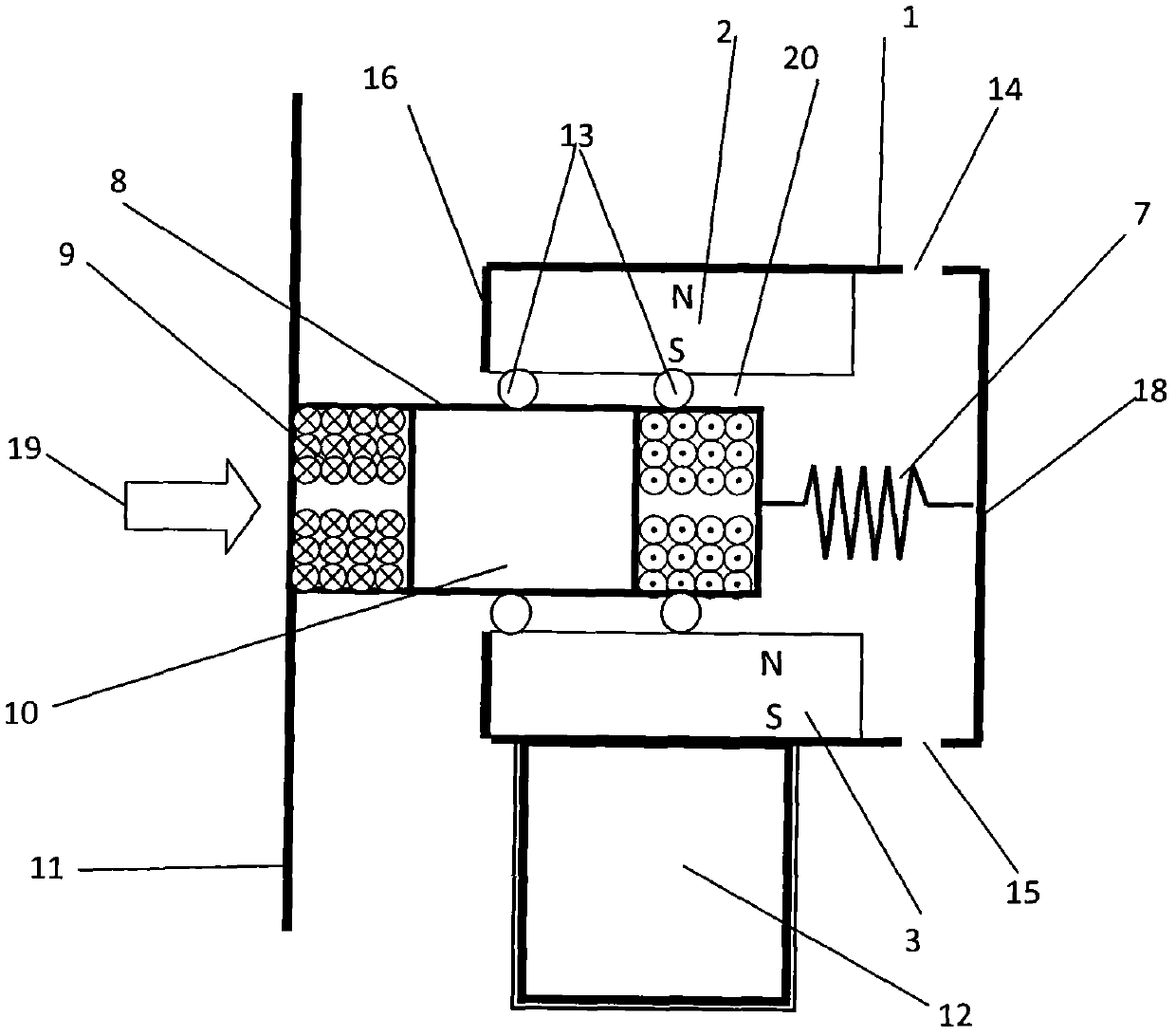
[0022] The piezoelectric generator of embodiment 2 is as figure 2 shown.

[0023] The structure of the generator is basically the same as that of Embodiment 1, except that the end of the excitation plate is provided with a trumpet-shaped water guide.

[0024] The outer dimensions of the generator box are 23cm long x 41cm wide x 9.6cm high, and are made of plastic plates with a thickness of 5mm; the outer dimensions of the coil box are 14.4cm long x 38cm wide x 5.4cm high. The scale of the excitation plate is 20cm high × 40cm wide × 0.1cm thick, which is made of plastic plates; the external dimensions of the permanent magnet are 13cm long × 38cm wide × 1cm high, and the material is neodymium iron boron (NdFeB) with a remanence of 1.3T NdFeB), its surface is coated with water-based acrylic anti-corrosion paint; the thickness of the gap between the coil box and the permanent magnet box is 0.6cm; the diameter of the smooth cylindrical rod is 0.5cm; the diameter of the drainage h...

Embodiment 3

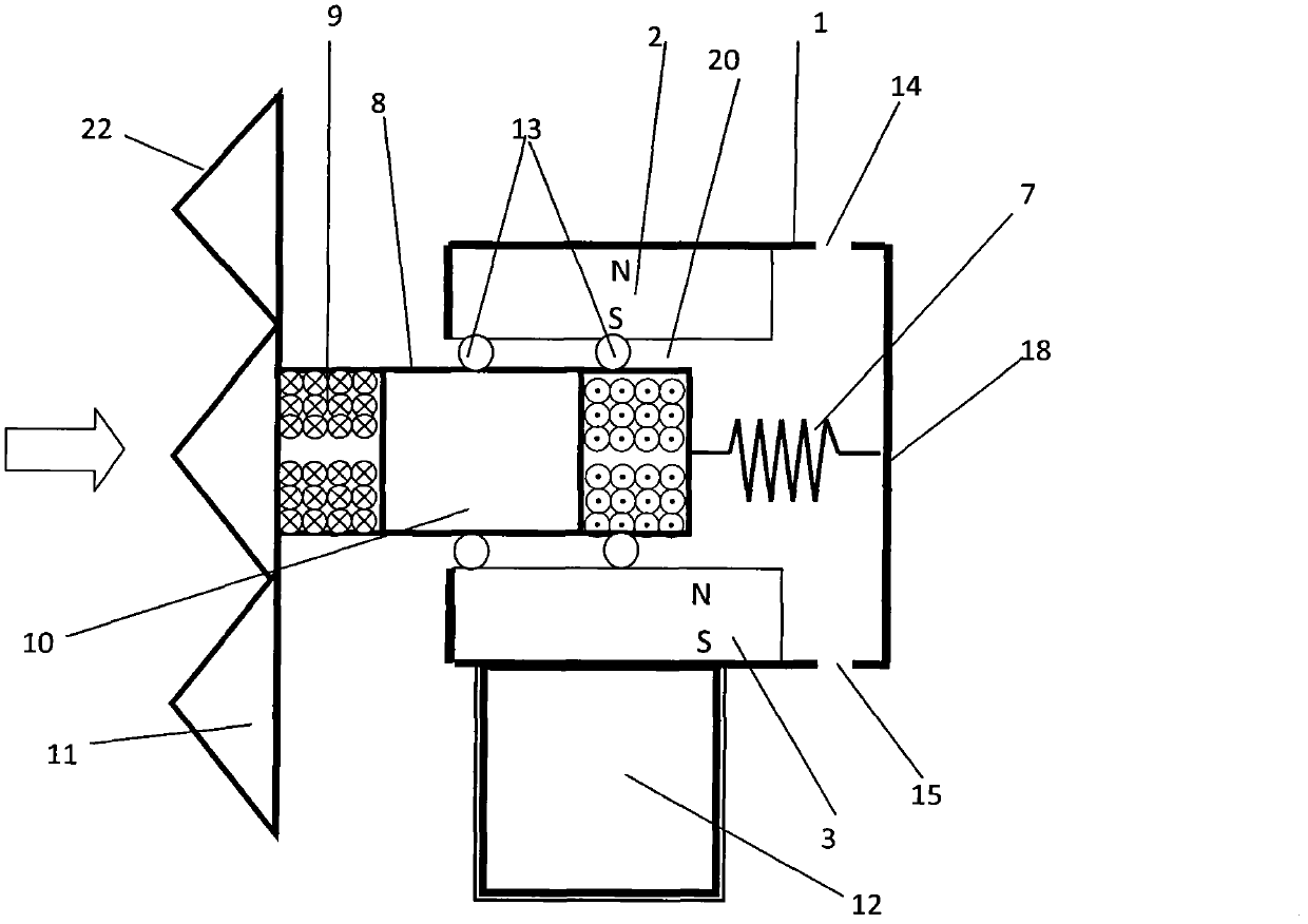
[0026] The piezoelectric generator of embodiment 3 such as image 3 shown.

[0027] The structure of the generator is basically the same as that of Embodiment 1, except that the end of the excitation plate is set in a bent and folded type.


PUM

PropertyMeasurementUnit
Spring constantaaaaaaaaaa

Abstract

The invention discloses an impact type vibration generator belonging to the technical field of vibration generation. The impact type vibration generator comprises a generator frame (1), two permanent magnets and a coil box (8), wherein the two permanent magnets are respectively fixed on the top surface and the bottom of the generator frame; the coil box (8) is positioned between the two permanent magnets, a second side wall opposite to a first side wall (18) of the generator frame is provided with an opening, one end of the coil box (8) is connected with the first side wall (18) by a first level spring (7), and the other end of the coil box (8) extends out of the generator frame through the opening and is connected with an excitation vibration plate (11). The impact type vibration generator has the other deformation structure that the first level spring (7) is replaced by a second level spring (4), one end of the second level spring (4) is fixed on the excitation vibration plate, and the other end of the second level spring is fixed on a second side wall (16) of a box body. The descriptive impact type vibration generator is of a flat shape, does not have rotating members, not only can use ocean current in the ocean, but also can use shallow water current in rivers and ditches to generate electricity and can reduce the adverse effect of the generator for the environment and maintenance cost at the same time.

Description

technical field [0001] The invention relates to an impact type vibration generator and a power generation method thereof, and relates to a device and a power generation method for generating power by utilizing water flow and its velocity fluctuation. Background technique [0002] In existing hydroelectric power generation technology, it is necessary to build a reservoir and use a generator with a water turbine. Among the existing tidal power generation technologies, the tidal dam technology also needs to build a reservoir and use a generator with a water turbine; while the tidal stream technology uses an underwater generator with a water turbine. In wave power generation technology, it is necessary to build a reservoir (TAPCHAN gradient channel wave capacity conversion method) or a closed cavity (OWC oscillating air column method) and use a generator with a water turbine or a steam turbine. Due to the need to build water storage units and use rotating parts, these technolog...

Claims


Application Information

Patent Timeline
IPC IPC(8): F03B13/14H02K35/04
CPCY02E10/38Y02E10/30
Inventor 胡俊辉赵淳生
Owner NANJING UNIV OF AERONAUTICS & ASTRONAUTICS
Why Eureka
Try Eureka