LCD panel display driving system and flexible circuit board thereof

A flexible circuit board and display driving technology, applied in nonlinear optics, static indicators, instruments, etc., can solve the problems of the speed of data transmission and the frequency of the clock, the lack of effective shielding, and the inability to manufacture liquid crystal screens. Achieve the effect of improving data transmission speed, reasonable circuit layout, and reducing electromagnetic interference

Inactive Publication Date: 2011-01-19
广东佳的美智能科技有限公司
View PDF4 Cites 12 Cited by
  • Summary
  • Abstract
  • Description
  • Claims
  • Application Information

AI Technical Summary

Problems solved by technology

The disadvantages of the existing LVDS interface are as follows: Since the LVDS interface uses a digital differential pair signal input, it cannot directly drive the Source Driver IC or Gate Driver IC of the LCD screen, and the speed of transmitting data and the frequency of the clock are also limited. The board light source cannot be directly driven by power supply, so a printed circuit board needs to be added on the back of the LCD screen, (the printed circuit board will have a T-CON digital processing chip, gamma circuit, Source Driver IC power supply system circuit, gamma power supply circuit, backlight drive circuit, VCOM circuit, etc.)
These circuits and printed circuit boards will increase the resource cost quite high, and at the same time, they cannot be effectively shielded on the back of the LCD screen, which will bring a lot of electromagnetic interference to the whole machine, and the printed circuit board circuit will generate a certain amount of heat when it is working. The use of the LCD screen has a certain impact. In addition, the height of the components on the printed circuit board cannot be reduced, which will add an irreducible thickness to the LCD screen, so that the LCD screen cannot be made thinner.

Method used


Image

  • LCD panel display driving system and flexible circuit board thereof
  • LCD panel display driving system and flexible circuit board thereof
  • LCD panel display driving system and flexible circuit board thereof

Examples


Embodiment Construction

[0015] In order to make the object, technical solution and advantages of the present invention clearer, the present invention will be further described in detail below in conjunction with the accompanying drawings.

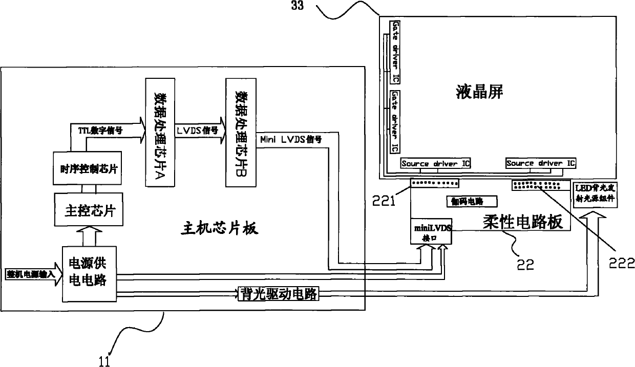
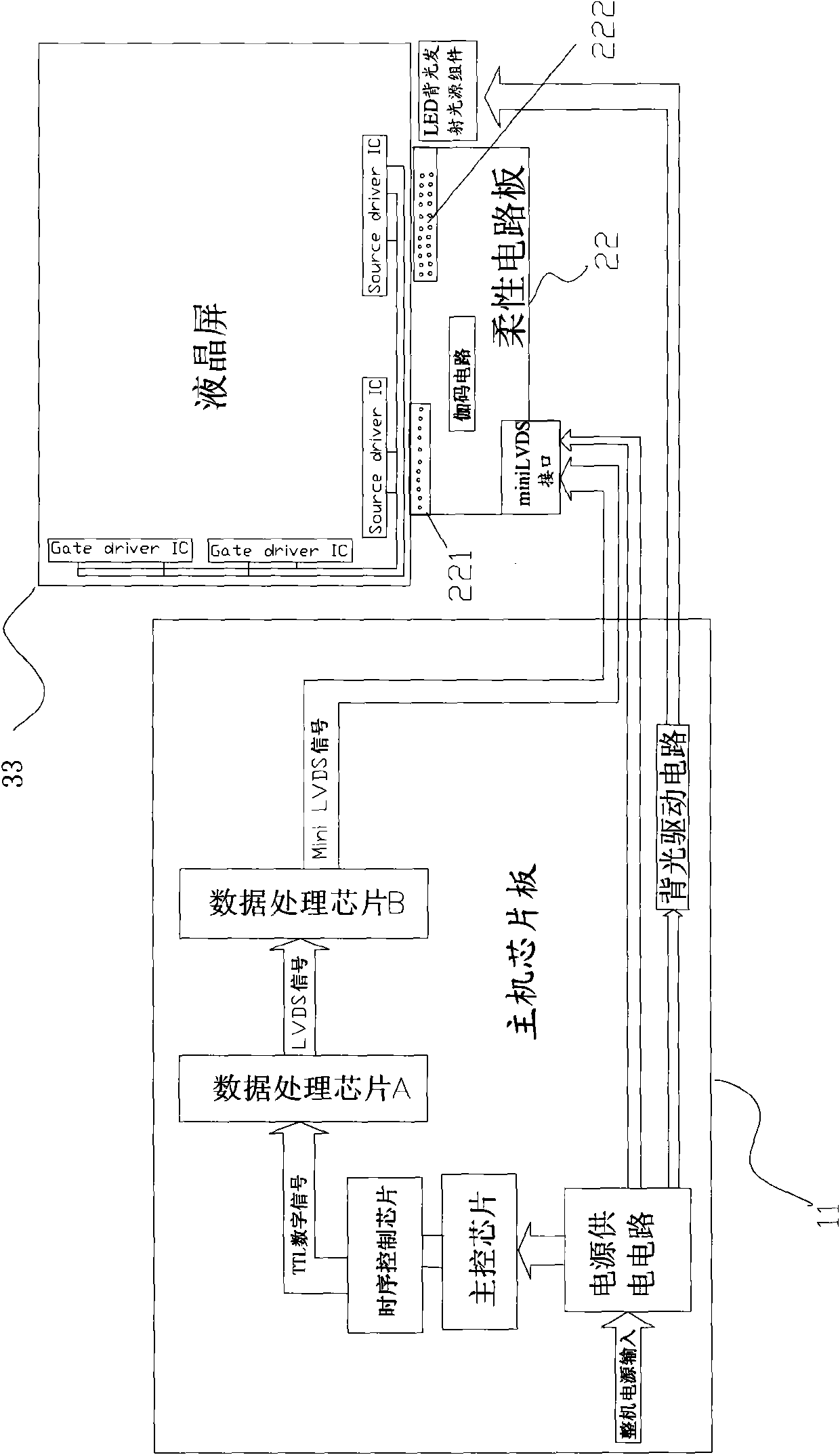
[0016] Such as figure 2 As shown, the present invention provides an embodiment of the present invention to provide a liquid crystal display drive system, including a host chip board 11, a flexible circuit board (FPC) 22, and a liquid crystal screen 33 connected in sequence; wherein the input of the flexible circuit board 22 The terminal is connected to the host chip board through the miniLVDS interface for data transmission, and the output terminal of the flexible circuit board is connected to the integrated circuit inside the LCD screen through two integrated FPC cable interfaces. A gamma circuit is also arranged in the flexible circuit board.

[0017] The host chip board is provided with a power supply circuit, a main control chip, a timing control chip, a bac...


PUM


Abstract

The invention discloses an LCD panel display driving system and a flexible printed circuit (FPC) thereof. The system comprises a host chip board, the FPC and an LCD panel which are connected in turn, wherein the input end of the FPC is connected with the host chip board through a mini low voltage differential signaling (LVDS) interface to perform data transmission; the output end of the FPC is connected with an integrated circuit in the LCD panel through two integrated FPC flat cable interfaces; and the inside of the FPC is provided with a gamma circuit. The LCD panel display driving system of the invention adopts the FPC with the miniLVDS interface so that the layout of the entire functional circuit is more reasonable, the circuit board on the back of the LCD panel can be eliminated and the connection ports and the product thickness can be reduced. Therefore, the manufacturing cost can be reduced more greatly, the electromagnetic interference on the product can be reduced more effectively; and the LCD panel is far from the back power supply emitting heat so as to have longer service life.

Description

technical field [0001] The invention relates to the field of electronic display products, in particular to a liquid crystal display drive circuit. Background technique [0002] In the existing liquid crystal screen display driving circuit, a separate liquid crystal screen rear circuit board is required to be connected to the liquid crystal screen. Such as figure 1 As shown, the existing liquid crystal display drive system includes a host chip board 1 , a circuit board 2 on the back of the liquid crystal screen, and a liquid crystal screen 3 . The back circuit board 2 of the liquid crystal screen is a hard printed circuit board, on which a power supply module, a Gamma circuit (Gamma circuit), a backlight drive circuit, a timing control chip, etc. are arranged, and there are many functional circuit modules and a complex structure. The input terminal of the circuit board 2 on the back of the LCD screen is connected to the host chip board 1 through the LVDS interface, and the ...

Claims


Application Information

Patent Timeline
Patent Type & Authority Applications(China)
IPC IPC(8): G09G3/36G02F1/13
Inventor 曾全王玉张志华
Owner 广东佳的美智能科技有限公司
Why Eureka
Try Eureka