Dual-rotor combined sand making machine

A double-rotor, sand making machine technology is applied to sand making machines. It can solve the problems of reduced efficiency, energy loss, and large consumption of wearing parts, so as to achieve the effects of reducing wear, improving efficiency, and reducing energy consumption.

Inactive Publication Date: 2011-01-26
松滋市中发机电实业有限公司
View PDF7 Cites 9 Cited by
  • Summary
  • Abstract
  • Description
  • Claims
  • Application Information

AI Technical Summary

Problems solved by technology

[0004] ①The problem of "one in and one out": stones are fed into the upper port of the jaw crusher, and materials are discharged from the lower port
A grain of sand wears out the entire tooth plate (wearable part), causing useless wear of the wearable part, resulting in a great economic loss
[0005] ②The problem of "the amount of extrusion is greater than the amount of impact": for impact type, impact type, hammer crusher and other types of sand making machines, the crushed stone is divided into two parts, one part is to accelerate the stone, and when it hits the wear-resistant The plate is crushed, and the other part is squeezed, ground and crushed by the rotating wear parts and the stationary wear parts.
The problem is: most of the stones are impacted but not broken, losing energy and reducing efficiency; the proportion of stones that are transferred to extrusion and crushing increases, and the wear of wear-resistant parts increases accordingly
This is the main reason why the existing sand making machine has high energy consumption, low output and large consumption of wearing parts.

Method used


Image

  • Dual-rotor combined sand making machine
  • Dual-rotor combined sand making machine

Examples


Embodiment Construction

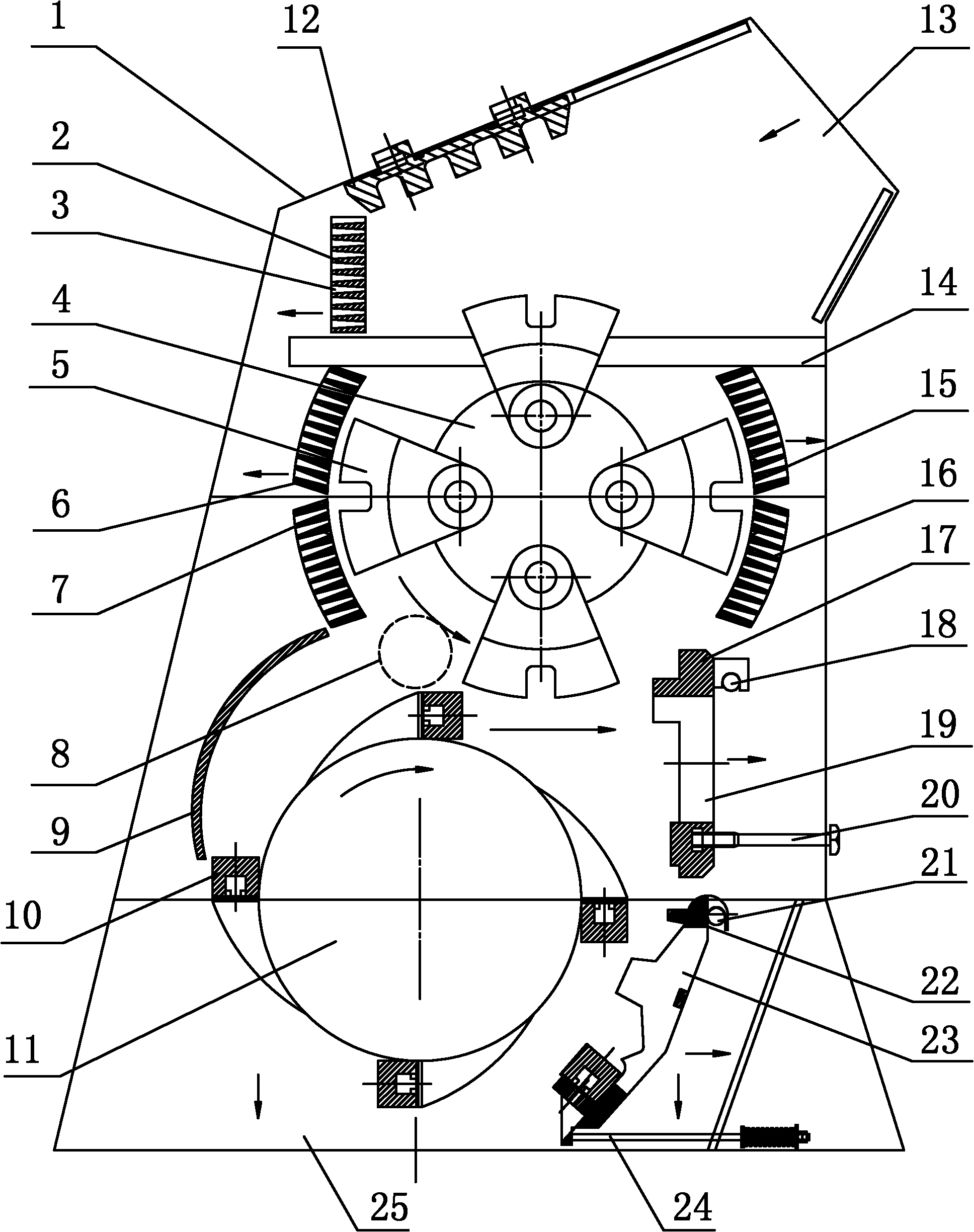
[0017] Such as figure 1 As shown, the double-rotor composite sand making machine includes a body 1, a first crushing plate 2, an upper rotor 4, a pendulum 5, a second crushing plate 6, a third crushing plate 7, a partition 9, a plate hammer 10, and a lower The rotor 11, the fourth crushing plate 12, the fifth crushing plate 15, the sixth crushing plate 16, the rotary drive device, the first screen plate, the second screen plate, the body 1 is a cavity, and the upper end of the body 1 is provided with a feed Port 13, the lower end of the body 1 is provided with a discharge port 25; the upper rotor (disc) 4 is located in the upper part of the cavity of the body 1, the upper rotor 4 is fixed on the upper rotating shaft, and the two ends of the upper rotating shaft are respectively The bearing is connected to the body 1 (that is, the upper rotating shaft can rotate). One end of the upper rotating shaft is located outside the body 1 and connected to the rotating drive device (the ro...


PUM


Abstract

The invention belongs to the field of machines for making sand from a mine and particularly relates to a sand making machine. A dual-rotor combined sand making machine comprises a machine body, a first crushing plate, an upper rotor, a pendulum bob, a second crushing plate, a third crushing plate, a fourth crushing plate, a fifth crushing plate, a sixth crushing plate, a rotary drive device, a first sieve plate and a second sieve plate and is characterized in that: a lower rotor is arranged below the upper rotor; the lower and upper rotors are arranged in a staggered way; and the lower rotor is fixed on a lower rotating shaft, the two end parts of the lower rotating shaft are connected with the machine body through bearings respectively, one end of the lower rotating shaft is positioned outside the machine body and connected with the rotary drive device, and a plate hammer is fixed on the lower rotor and along the circle edge. The sand making machine has the characteristics of low energy consumption, reduced wear and high efficiency.

Description

Technical field [0001] The invention belongs to the field of mining sand and stone machinery, and specifically relates to a sand and stone making machine. technical background [0002] Stones are made into sand. There are mainly two methods of grinding sand (for example, roller sand making machine) and impact sand making (for example, impact crusher, impact crusher) in the existing technical fields at home and abroad. . Grinding technology has high wear, energy consumption, low output and low efficiency; impact and impact technology cannot increase the speed of stone impact, the rate of stone crushing is low, and the production efficiency of sand making is not high. This is the current technical problem of high power consumption, high consumption of metal materials, low output and high sand production cost in the sand production field. [0003] At present, there are two key points in the process technology problems of sand making machines at home and abroad: [0004] ①The problem ...

Claims


Application Information

Patent Timeline
Patent Type & Authority Applications(China)
IPC IPC(8): B02C13/02B02C13/28B02C13/30B02C23/08
Inventor 田野李华平王宇
Owner 松滋市中发机电实业有限公司
Why Eureka
Try Eureka