
Relay protection device detection circuit

A technology of a relay protection device and a detection circuit, which is applied in the field of circuits, can solve the problems of excessive wear of circuit components, increase of current, burnt out optocouplers, etc., and achieve the effect of ensuring normal operation.

Inactive Publication Date: 2011-01-26
深圳市华力特电气有限公司
View PDF4 Cites 21 Cited by
  • Summary
  • Abstract
  • Description
  • Claims
  • Application Information

AI Technical Summary

Problems solved by technology

[0005] With this circuit structure, when the detection voltage increases, resulting in reverse breakdown of the Zener diode, since the loop resistance in the circuit is a fixed value, if the detection voltage continues to increase, the reverse breakdown voltage will be loaded on the loop resistance, As a result, the current in the loop continues to increase, which will cause the following problems:
[0006] 1. The isolated output circuit is generally isolated by an optocoupler, and the diode end of the optocoupler generally has a certain limit on the current input. If the current continues to increase, the optocoupler may be burned;
[0007] 2. According to the power calculation formula: P=I×U, if the current in the loop continues to increase, and the reverse voltage in the loop also increases, the power consumption in the entire voltage stabilizing circuit will increase sharply, resulting in the loss of components in the circuit too fast

Method used


Image

  • Relay protection device detection circuit
  • Relay protection device detection circuit
  • Relay protection device detection circuit

Examples


Embodiment Construction

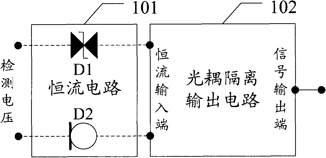
[0014] An embodiment of the present invention provides a detection circuit for a relay protection device, which is used to ensure normal operation of circuit elements in the detection circuit when the detection voltage increases.

[0015] see figure 1 , the detection circuit in the embodiment of the present invention mainly includes the following parts:

[0016] The constant current circuit 101, the input terminal of the constant current circuit is connected with a detection voltage, and the detection voltage is the input voltage of the circuit protected by the relay protection device.

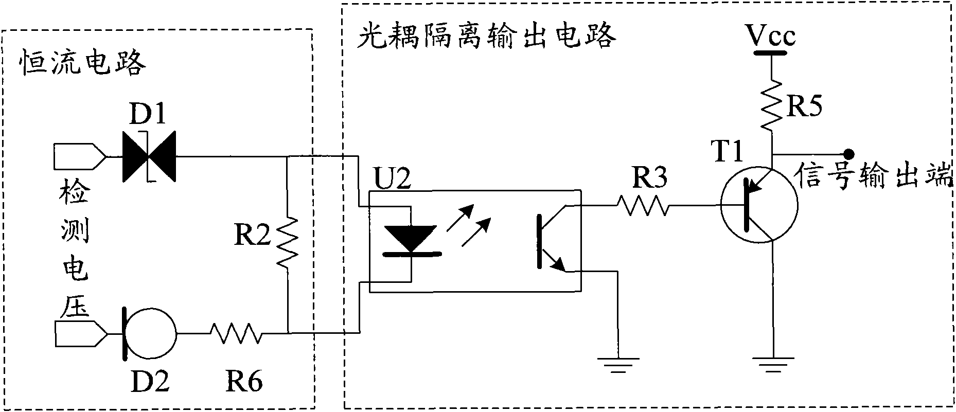
[0017] The constant current circuit includes: a transient diode (D1) and a constant current diode (D2), and the transient diode (D1) is connected in series with the constant current diode (D2).

[0018] The transient diode (D1) is used to provide the threshold voltage and share the input detection voltage; the constant current diode (D2) is used to provide a stable current for the detection c...


PUM


Abstract

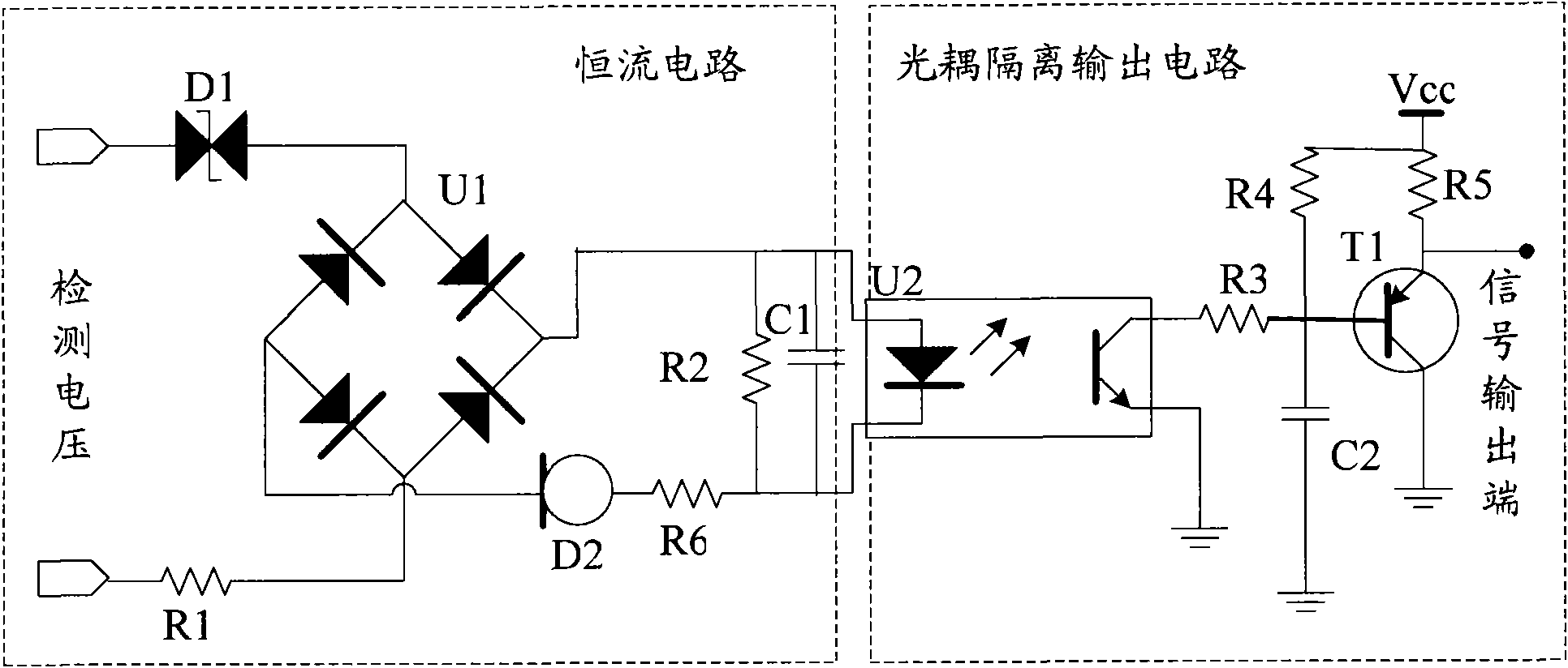
The embodiment of the invention discloses a relay protection device detection circuit, which is used for ensuring normal work of a circuit element in the detection circuit when voltage boosting is detected. The detection circuit of the embodiment of the invention comprises a constant current circuit and an optical coupler isolating output circuit, wherein an input end of the constant current circuit is connected with detection voltage; the input end of the optical coupler isolating output circuit is connected with the output end of the constant current circuit; the constant current circuit comprises a transient diode (D1) and a constant current diode (D2) which are connected in series; the transient diode (D1) is used for providing threshold voltage and allocating the input detection voltage; the constant current diode (D2) is used for providing stable current for the detection circuit; and the optical coupler isolating output circuit is used for transmitting a low-voltage control signal. In addition, the detection circuit can realize compatibility of input of alternating current detection voltage and direct current detection voltage by improvement.

Description

technical field [0001] The invention relates to the field of circuits, in particular to a detection circuit for a relay protection device. Background technique [0002] In the power protection industry, relay protection devices are widely used and indispensable. Whether it is as small as some electric devices (such as generators, power supply lines), or as large as the entire power system, relay protection devices are required to provide fault warning signals, or directly and automatically control circuit breakers to issue trip instructions to ensure the safety of power equipment . [0003] Due to the wide application of relay protection devices, the range span of its protection voltage is also very large. A detection circuit is needed to convert the high-voltage signal in the protection circuit into a low-voltage control signal, so as to facilitate the control of computers or some intelligent electronic devices. [0004] In the prior art, the general detection circuit ado...

Claims


Application Information

Patent Timeline
IPC IPC(8): G01R31/00G01R1/36
Inventor 文小龙董光府程许平张宝贵罗良庆
Owner 深圳市华力特电气有限公司
Learn More