Circuit and method for measuring battery electric quantity

A battery power measurement technology, applied in the direction of measuring electrical variables, measuring electricity, measuring devices, etc., can solve problems that affect the company's reputation, weak leakage current, and power consumption

Active Publication Date: 2011-01-26
QUANTA COMPUTER INC
View PDF3 Cites 5 Cited by
  • Summary
  • Abstract
  • Description
  • Claims
  • Application Information

AI Technical Summary

Problems solved by technology

[0003] Integrating the traditional separate battery module into the electronic device reduces the volume and weight, but the battery module is fixedly coupled to the electronic device and cannot be replaced by consumers
When the notebook computer integrating the battery module is not operating, the coupling relationship between the battery module and the electronic device causes the battery module to generate leakage current and consume power
In addition, the leakage current is quite weak, for example, less than the current deadband. Therefore, the leakage current is regarded as noise by the battery module and ignored, so that consumers cannot truly know the battery capacity of the battery module.
[0004] In this way, if the battery power of the battery module has been consumed during the delivery of the electronic device to each store and placed in the warehouse, and when the consumer finds that the battery module is out of power after purchasing, the transformer (Adaptor) is used to power the electronic device. After booting up, because the battery module corresponds to the state that the electronic device still has power before leaving the factory, the screen of the electronic device after starting up shows that the battery module is in a state of power, which makes consumers mistakenly believe that the battery module or electronic device is a defective product , thus causing frequent customer complaints of various enterprises, and seriously affecting the company's reputation

Method used


Image

  • Circuit and method for measuring battery electric quantity
  • Circuit and method for measuring battery electric quantity
  • Circuit and method for measuring battery electric quantity

Examples


Embodiment Construction

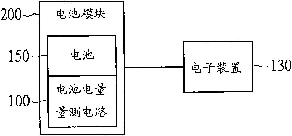
[0034] An embodiment of a battery power measurement circuit applied to a battery module is described as follows, please refer to figure 1 , which shows a schematic diagram of a battery power measuring circuit according to an embodiment of the present invention applied to a battery module. Such as figure 1 As shown, the battery power measurement circuit 100 is, for example, applied in a battery module 200 , the battery module 200 includes a battery 150 , and the battery module 200 supplies power to the electronic device 130 during operation. The electronic device 130 is, for example, a notebook computer.

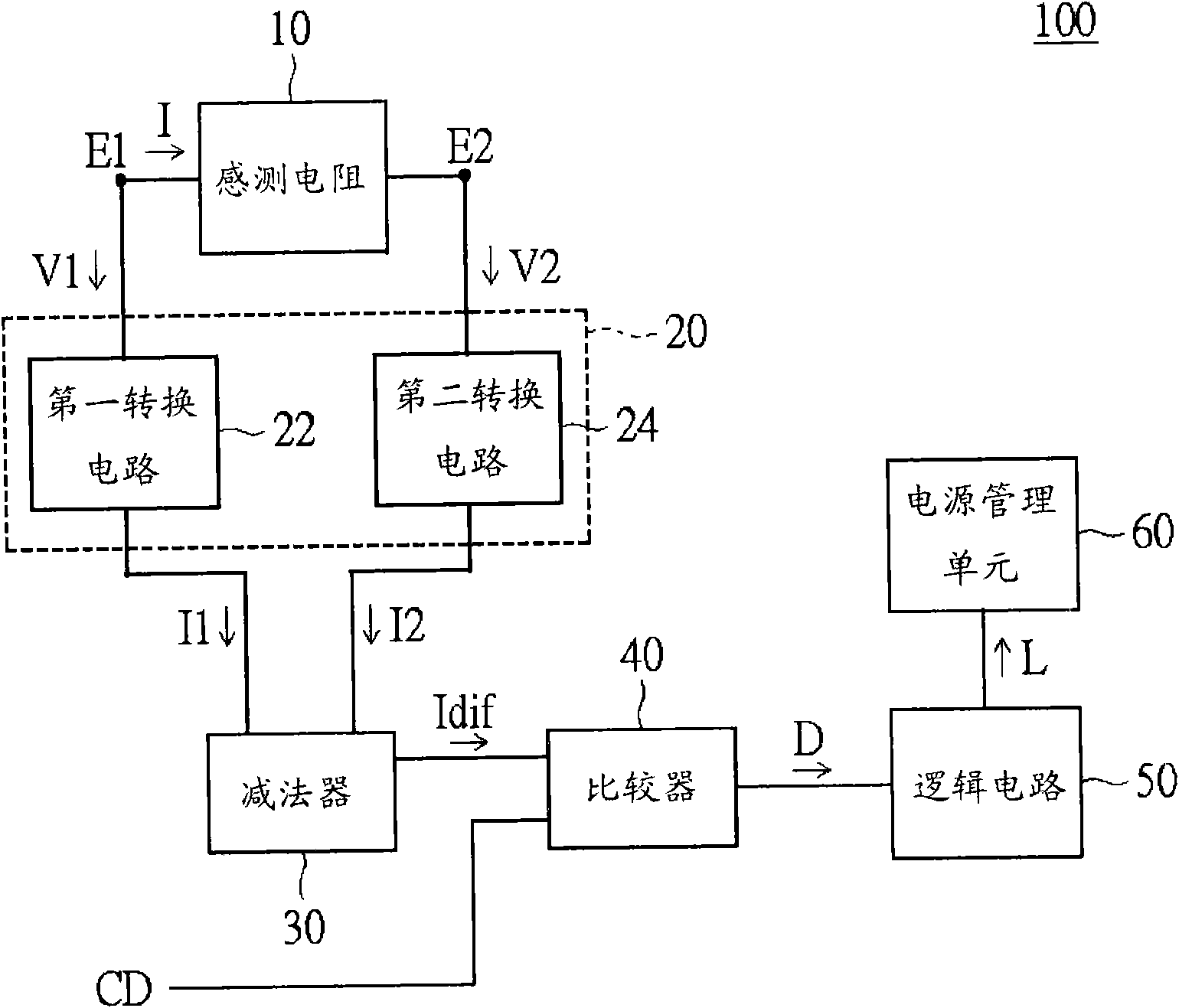
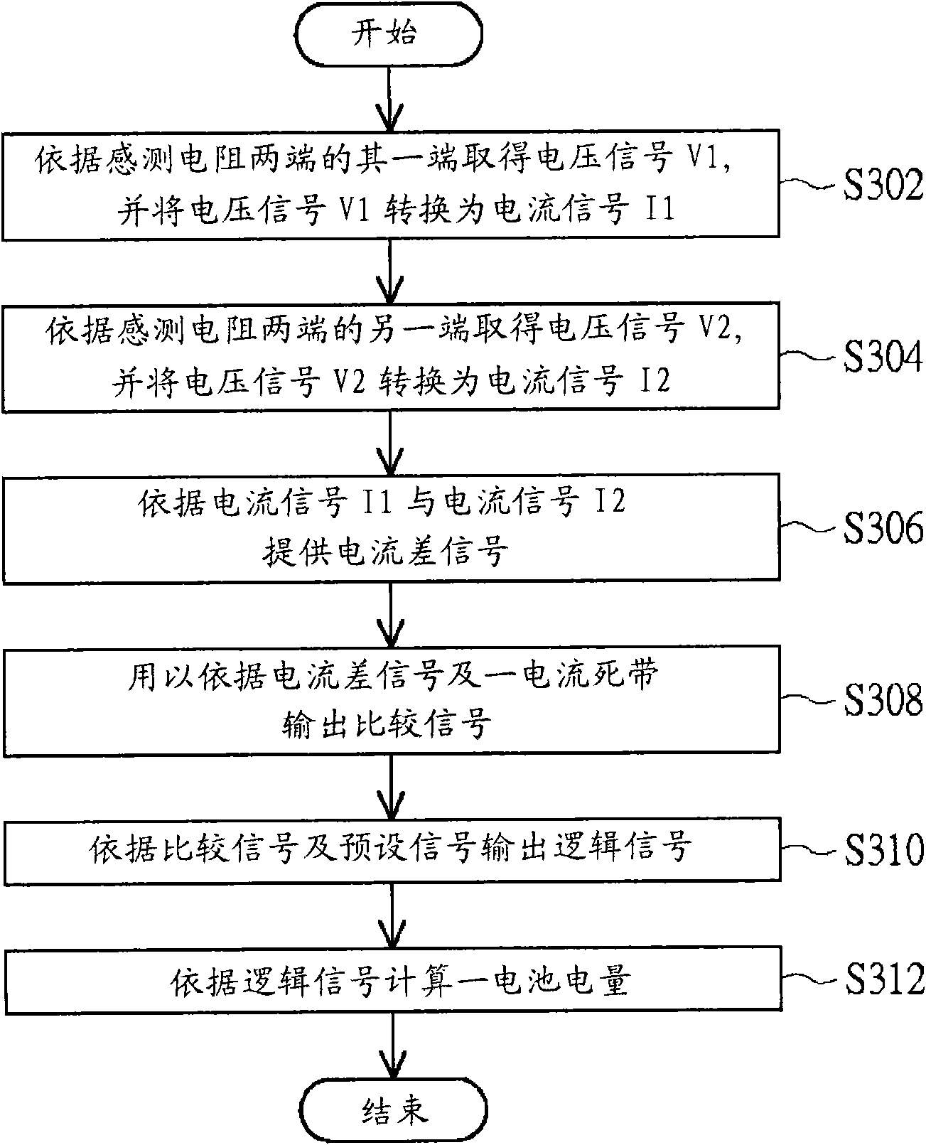
[0035] Please also refer to figure 2 and image 3 , figure 2 show figure 1 The block diagram of the battery power measurement circuit. image 3 A flow chart of a method for measuring battery power is shown. The battery power measurement circuit 100 includes a sensing resistor 10 , a voltage-to-current conversion circuit 20 , a subtractor 30 , a comparator 40 , a logi...


PUM


Abstract

The invention relates to a circuit and a method for measuring battery electric quantity. The circuit comprises a sensing resistor, a voltage and current converting circuit, a subtractor, a comparer, a logic circuit and a power supply management unit, wherein a first conversion circuit of the voltage and current converting circuit obtains a first voltage signal according to one end of two ends of the sensing resistor and converts the first voltage signal into a first current signal; a second conversion circuit of the voltage and current converting circuit obtains a second voltage signal according to the other end of two ends of the sensing resistor and converts the second voltage signal into a second current signal; the subtractor provides a current difference signal according to the firstcurrent signal and the second current signal; the comparer outputs a comparison signal according to the current difference signal and the current dead band; the logic circuit outputs a logic signal according to the comparison signal and a preset signal; and the management unit calculates the battery electric quantity according to the logic signal.

Description

technical field [0001] The present invention relates to a battery power measuring circuit and its method, in particular to a battery power measuring circuit and its method for calculating the actual battery power by recording the leakage current of the coupled battery. Background technique [0002] In today's era of ever-changing technology, with the popularization of electronic devices, in addition to consumers' requirements for the functions of electronic devices, various companies also try to make electronic devices thinner and lighter to meet consumers' needs for portable electronic devices. need. The electronic device is, for example, a notebook computer. In this way, various enterprises, for example, change the traditional separation method (such as separating the notebook computer from the battery module) to an integrated method (the battery module is fixedly coupled to the notebook computer), so as to reduce the size and weight of the notebook computer. [0003] In...

Claims


Application Information

Patent Timeline
Patent Type & Authority Applications(China)
IPC IPC(8): G01R31/36
Inventor 颜维廷
Owner QUANTA COMPUTER INC
Why Eureka
Try Eureka