
Load identification interactive whiteboard and method for implementing same

An electronic whiteboard and load identification technology, applied in the field of electronic information, can solve the problems of being affected by strong light and dust, poor durability, and high cost, and achieve the effects of simple installation, debugging and maintenance, good adaptability, and reliable equipment.

Inactive Publication Date: 2011-01-26
NANJING UNIV OF AERONAUTICS & ASTRONAUTICS
View PDF3 Cites 15 Cited by
  • Summary
  • Abstract
  • Description
  • Claims
  • Application Information

AI Technical Summary

Problems solved by technology

[0007] Disadvantages: poor durability, fear of scratches, slow response speed, unable to make a large area, whiteboard pen does not support functions such as the right mouse button, and it is difficult to operate the computer
[0011] Disadvantages: high cost, special pen must be used, no pressure response
[0015] Disadvantages: You must use a special pen and cannot do touch operations
[0019] Cons: No pressure response, affected by strong light and dust
Ultrasonic positioning technology has no special requirements for whiteboards, and it is easy to realize large-format production, but it has high requirements for components. The performance requirements of components of a pair of ultrasonic detectors must be consistent, which is difficult to achieve in practical applications; components are easily affected by temperature changes. , the positioning stability is poor; a special pen is required, and a laser is usually required on the pen to indicate the target. At the same time, the diffuse reflection light on the whiteboard is also used to notify the ultrasonic receiver to start timing. The technology is complex and difficult to debug and maintain.

Method used

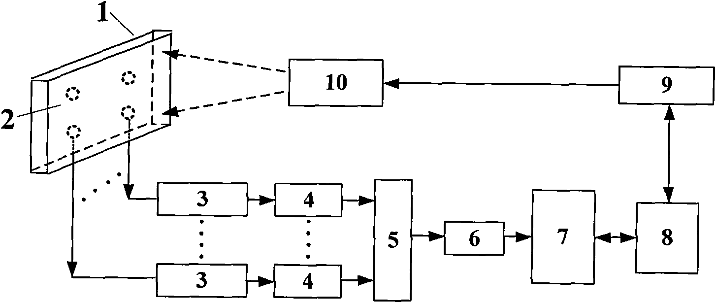

Image

  • Load identification interactive whiteboard and method for implementing same
  • Load identification interactive whiteboard and method for implementing same
  • Load identification interactive whiteboard and method for implementing same

Examples


Embodiment Construction

[0064] 1) The workflow of the interactive whiteboard

[0065] The interactive whiteboard not only serves as the display area of ​​the projector, but also replaces the mouse as the interactive device between the user and the PC. The operation of the whiteboard pen on the whiteboard is equivalent to the operation of the mouse on the PC screen. Therefore, to use an interactive whiteboard, you should first establish the corresponding relationship between the projected display area and the PC screen. This process is called positioning. Only after the whiteboard is positioned can the position of the whiteboard correspond to the coordinates of the PC screen, and the operations on the whiteboard can be correctly mapped to the PC screen, so that the mouse projected on the whiteboard can track the position of the whiteboard markers. Let users feel that using a pen on a whiteboard is like using a mouse to operate on a screen.

[0066] When the interactive whiteboard is positioned, it u...


PUM


Abstract

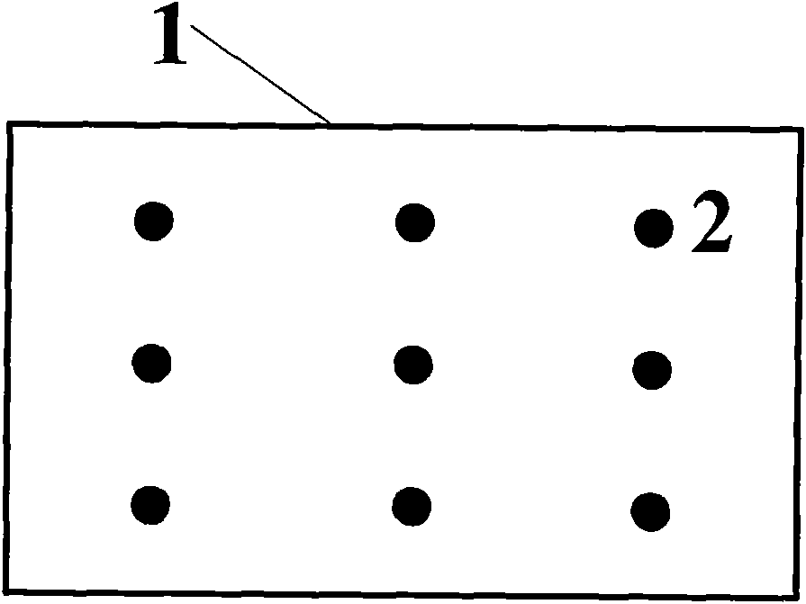
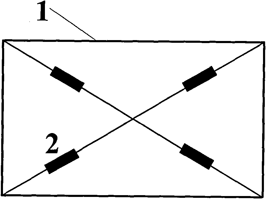
The invention discloses a method for implementing a load identification interactive whiteboard, and belongs to the field of electronic information. A load identification interactive whiteboard system comprises a whiteboard (1), a mechanical sensor (2), a transmitter (3), an amplifier (4), a multi-way switch (5), an A / D sampling module (6), a data processing module (7), a communication module (8), a PC machine (9) and a projector (10). In the method, the mechanical sensor is used as a sensing element of the interactive whiteboard, and after sensor data is normalized by testing the multipoint deformation of the whiteboard, the positioning of contacts and the expression of stroke thickness are realized by using the technology of pattern recognition. The interactive whiteboard manufactured by the method has the advantages of simple structure, high reliability, low installation and maintenance requirements, low cost, high adaptability, easy implementation of large-layout manufacturing, no need of special pens and the like, and the method also can be used for manufacturing touch screens.

Description

1. Technical field [0001] The interactive electronic whiteboard based on load recognition technology of the present invention belongs to the field of electronic information, and relates to the application of mechanics, sensor technology and pattern recognition technology on the electronic whiteboard and touch screen. 2. Background technology [0002] The interactive electronic whiteboard can communicate with the computer, connect the electronic whiteboard to the PC, and use the projector to project the content on the PC to the electronic whiteboard screen. With the support of special applications, a large screen, Interactive collaborative meeting or teaching environment. Use a specific positioning pen instead of the mouse to operate on the whiteboard, run any application, edit, annotate, save files, and any operations that can be achieved with the keyboard and mouse on the computer. [0003] Interactive electronic whiteboards mainly include the following types according to ...

Claims


Application Information

Patent Timeline
IPC IPC(8): G06F3/041G06N3/02
Inventor 曾捷潘晓文刘宏月徐海伟张少华
Owner NANJING UNIV OF AERONAUTICS & ASTRONAUTICS
Learn More