Coil panel terminal

A coil disc and terminal technology, applied in the direction of multi-core cable end parts, electrical components, etc., can solve the problems of easy interference between the lead wire and the coil disc bracket, easy oxidation of aluminum wire, difficult to clean with silicone glue, etc. The effect of coil tray bracket interference, environmental protection requirements, and easy assembly

Active Publication Date: 2011-01-26
MIDEA GRP CO LTD
View PDF2 Cites 0 Cited by
  • Summary
  • Abstract
  • Description
  • Claims
  • Application Information

AI Technical Summary

Problems solved by technology

[0002] Coil coils of existing induction cookers are generally made of copper wire harness or aluminum wire harness. The lead wire process of the copper wire harness coil coil needs to be tinned first and then welded to the control board. At the same time, silicone glue is added to better fix the lead wires on the control panel On the board; the aluminum wire harness coil plate must be welded to the control board by crimping the aluminum wire harness with lead terminals due to the easy oxidation of aluminum wires and the difficulty of tinning, and it is still necessary to add silicone glue to fix the leads better; These two methods of fixing coil coil lead wires are relatively backward. Not only are the processes cumbersome, but the environment of the gluing work station on the production line is poor. It is difficult to clean the silicone glue if rework is required, and the lead wires fixed on the control board are prone to contact with the coil. Disc holder interference problem

Method used


Image

  • Coil panel terminal
  • Coil panel terminal
  • Coil panel terminal

Examples


Embodiment Construction

[0014] The present invention will be further described below in conjunction with drawings and embodiments.

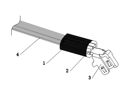
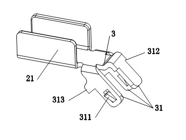
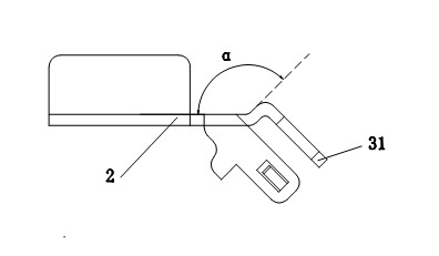
[0015] Such as figure 1 , figure 2 , image 3 As shown, the coil disk terminal of the present invention includes a heat shrinkable sleeve 1, a lead wire crimping part 2 and a plug terminal 3 connected to the end of the lead wire crimping part 2, wherein the lead wire crimping part 2 includes two vertically upward The crimping piece 21, the crimping piece 21 is crimping the lead wire 4, and the heat shrinkable sleeve 1 is set on the outside of the lead wire crimping part 2. The plug terminal 3 includes three pins 31 arranged in the shape of "pin", The pin 31 at the top of the "pin" shape is bent upwards to form an angle α with the plane of the crimping part 2 of the lead wire, and then bent downwards at 90°. Insertion limiters 312 are arranged on both sides of the root. This structure enables The lead wires of the coil plate are exported out of its support, effective...


PUM


Abstract

The invention discloses a coil panel terminal, which comprises a heat-shrinkable tubing, a lead compression joint part and a plugging terminal connected with the end part of the lead compression joint part, wherein the lead compression joint part comprises two compression joint pieces which bend upward; and after the compression joint pieces compress a lead, the heat-shrinkable tubing is sleeved outside the lead compression joint part. The coil panel terminal is characterized in that: the plugging terminal comprises three pins which are arranged in a triangular form; the pin on the top of thetriangular form bends upward to form an included angle alpha with the plane of the lead compression joint part and then bends 90 DEG C downward; the head parts of the two opposite pins at the bottom of the triangular form are provided with strip outward elastic inverted hooks; plugging limiting platforms are arranged at the root parts of the pins inwards; and the plugging terminal is fastened on a control panel by the elastic inverted hooks and the plugging limiting platform. In the invention, the process for fixing the lead of the coil panel by applying silicone adhesive in a production lineis not adopted, the environment-protection requirements are well met, the assembly is convenient, the fixation is firm, the welded lead of the coil panel can be led out of the support, and the problems such as the interference of the lead with the support of the coil panel are solved effectively.

Description

technical field [0001] The invention relates to a coil disk terminal, which belongs to the improvement technology of the coil disk terminal structure. Background technique [0002] Coil coils of existing induction cookers are generally made of copper wire harness or aluminum wire harness. The lead wire process of the copper wire harness coil coil needs to be tinned first and then welded to the control board. At the same time, silicone glue is added to better fix the lead wires on the control panel On the board; the aluminum wire harness coil plate must be welded to the control board by crimping the aluminum wire harness with lead terminals due to the easy oxidation of aluminum wires and the difficulty of tinning, and it is still necessary to add silicone glue to fix the leads better; These two methods of fixing coil coil lead wires are relatively backward. Not only are the processes cumbersome, but the environment of the gluing work station on the production line is poor. It...

Claims


Application Information

Patent Timeline
Patent Type & Authority Applications(China)
IPC IPC(8): H01R11/11H01R12/34
Inventor 英俊民姚勇歧周勤刘昌勇
Owner MIDEA GRP CO LTD
Why Eureka
Try Eureka