
A welding tool for friction stir welding of angled joints

A technology of friction stir welding and friction stir, which is applied in welding equipment, manufacturing tools, non-electric welding equipment, etc., can solve the problems that special-shaped joints cannot be welded, and achieve the effects of high internal quality, smooth weld surface and high joint strength

Active Publication Date: 2020-10-16
SHANGHAI AEROSPACE EQUIP MFG GENERAL FACTORY
View PDF6 Cites 0 Cited by
  • Summary
  • Abstract
  • Description
  • Claims
  • Application Information

AI Technical Summary

Problems solved by technology

Due to the limitation of traditional friction stir welding technology, the integrated design of stirring pin and shoulder cannot realize the welding of special-shaped joints, such as corner joints and T-shaped joints

Method used


Image

  • A welding tool for friction stir welding of angled joints
  • A welding tool for friction stir welding of angled joints
  • A welding tool for friction stir welding of angled joints

Examples


Embodiment Construction

[0018] Hereinafter, the present invention will be further described in conjunction with the drawings and embodiments.

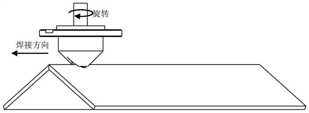
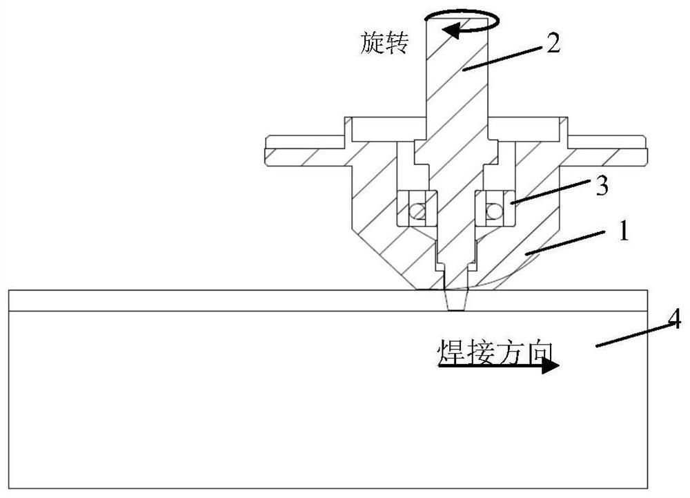
[0019] Combined with the accompanying drawings, figure 1 Schematic diagram of static shoulder friction stir welding of corner joint, shoulder 1 is stationary, stirring needle 2 rotates, welding front shoulder 1 is away from the welding surface, and the back is firmly attached to workpiece 4, as shown in figure 2 shown. The relative movement between the shaft shoulder 1 and the stirring needle 2 is realized through the bearing 3, and the rigidity of the stirring needle 2 is guaranteed. During welding, the joint form of the shaft shoulder profile 12 and the workpiece 4 is consistent, and the shape of the formed weld seam is consistent with that before welding.

[0020] image 3 The structural diagram of the shaft shoulder shown in the figure shows that along the welding direction, the front end is opened in a boat shape to reduce resistance, and the rear en...


PUM


Abstract

The invention discloses a friction stir welding tool for a reflex angle joint. The welding tool comprises a shaft shoulder, a stirring needle and a bearing. The shaft shoulder and the stirring needleachieve relative movement through the bearing, the stirring needle rotates, the shaft shoulder is stationary, and the welding tool is used for friction stir welding of the reflex angle (larger than 180 degrees) joint. The shaft shoulder is in a special shape like a streamline shape in the welding direction, the welding front end is opened in a ship shape, the welding resistance is reduced, the rear end is firmly attached to the joint, and the effects of rolling and weld line forming are achieved; the shaft shoulder is in a reflex angle approximate to the joint in the welding seam cross sectiondirection, and the profile characteristics of wrapping materials are achieved. The stirring needle and the shaft shoulder are coaxially assembled, a suitable clearance exists between the stirring needle and the shaft shoulder, and a special thread structure and a plastic material retention space are designed. By means of the friction stir welding tool, friction stir welding for the reflex angle joint can be realized, the weld seam maintains the reflex angle shape, the weld seam almost has no thinning and the surface is smooth.

Description

technical field [0001] The invention relates to friction stir welding of corner joints, in particular to the friction stir welding of workpieces of corner joints, which can realize the friction stir welding of corner joints, maintain the shape of weld seams without thinning. Background technique [0002] At present, friction stir welding is a new type of solid-phase welding technology, which has the advantages of high strength, low stress deformation, and green welding. It is widely used in aluminum alloy, magnesium alloy, and copper alloy components, but most of the joints are butt joints. , Lap joint form. Due to the limitation of traditional friction stir welding technology, the integrated design of stirring needle and shaft shoulder cannot realize the welding of special-shaped joints, such as corner joints and T-shaped joints. With the development of static shoulder technology, the friction stir welding of corner joints and T-shaped joints becomes possible due to the st...

Claims


Application Information

Patent Timeline
Patent Type & Authority Patents(China)
IPC IPC(8): B23K20/12
CPCB23K20/122
Inventor 夏佩云尹玉环董吉义李丹周培培许辉汤化伟徐奎髙嘉爽
Owner SHANGHAI AEROSPACE EQUIP MFG GENERAL FACTORY
Learn More