Piercing connecting conductor and device for connecting or tapping insulated wire thereof

A technology for connecting conductors and insulated wires, which is applied in the directions of needle tip/slotted plate contacts, clamping/spring connections, and tightening/insulating connectors used to penetrate insulated wires/cable core wires. The sawtooth structure of the contact structure has problems such as large resistance, small metal sheet carrying current, which is not conducive to cutting through the insulating layer, etc., to achieve the effect of saving labor and material costs, easy insulation connection and tap work, and reducing the incidence of line faults and electric shock accidents.

Inactive Publication Date: 2011-01-26
XIAN OCAME ELECTRIC
View PDF5 Cites 1 Cited by
  • Summary
  • Abstract
  • Description
  • Claims
  • Application Information

AI Technical Summary

Problems solved by technology

[0012] 1. It can only cut through insulated wires with small wire diameters. The carrying current of the metal sheet is small and the withstand voltage is low. It is mainly suitable for cutting through weakly insulated wires, such as: telephone lines, network cables, etc.
[0013] 2. Compared with the sawtooth structure, the metal sheet contact structure has greater resistance, which is not conducive to cutting through the insulation layer of thick or hard insulated wires, especially when the metal sheet is thick
[0014] 3 This technology can only realize the plugging of insulated wires with general electrical equipment, telephones, and computer interfaces through metal sheets, but cannot directly connect or tap two or more insulated wires

Method used


Image

  • Piercing connecting conductor and device for connecting or tapping insulated wire thereof
  • Piercing connecting conductor and device for connecting or tapping insulated wire thereof
  • Piercing connecting conductor and device for connecting or tapping insulated wire thereof

Examples


Embodiment 1

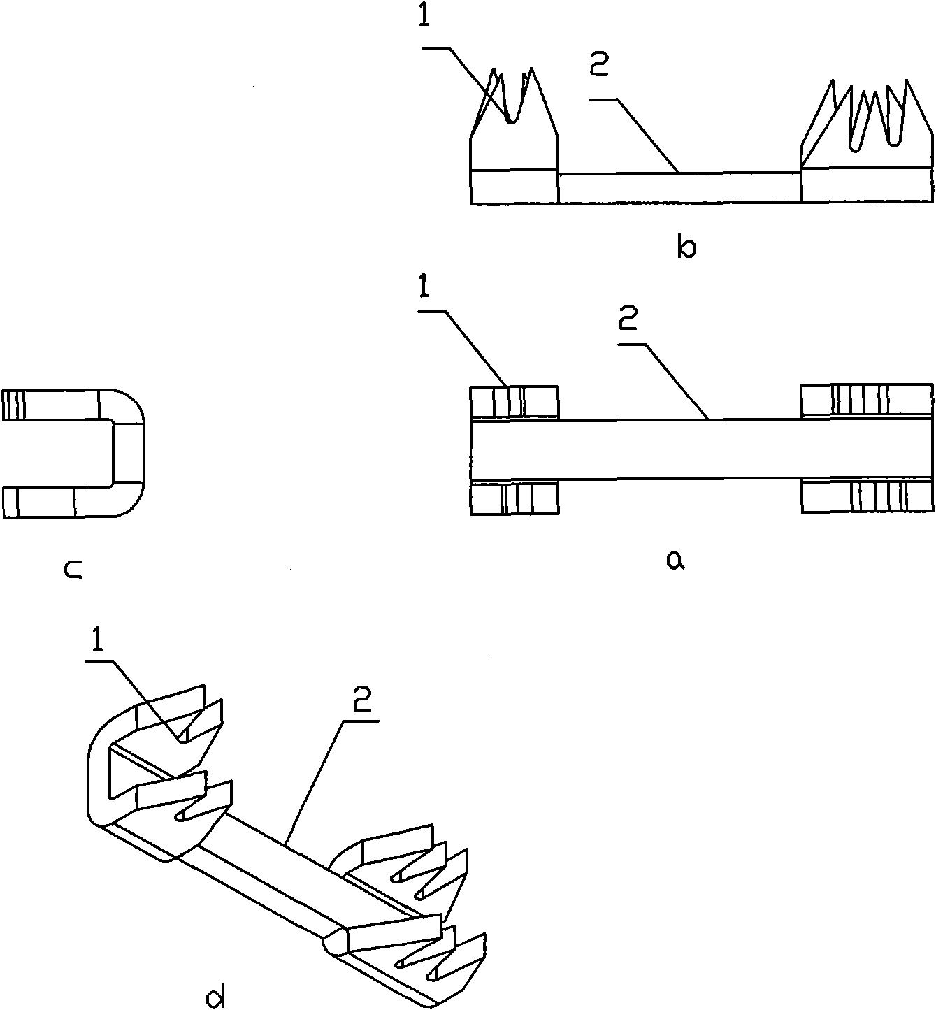
[0039] Such as figure 2 As shown, a piercing connection conductor is provided, wherein the views a, b, c, d are respectively the main view, top view, side view and perspective view, which include the connection conductor 2, and a V-shaped and A W-shaped two piercing contacts 1, the same two piercing contacts are arranged in two parallel rows along the connecting conductor, and a U-shape is formed between the two rows (see view c), of course, more than two rows can also be arranged , such as three rows, four rows, etc.; the piercing contact 1 and the connecting conductor 2 are made of conductive materials, and the connecting conductor 2 and the piercing contact 1 are electrically connected, and the piercing contact 1 can pierce through the Insulation layer of insulated wires to realize the connection or tap of insulated wires.

[0040] As another example, it can be seen from view b that the two rows of piercing contacts are asymmetrical and staggered, so that the staggered ar...

Embodiment 2

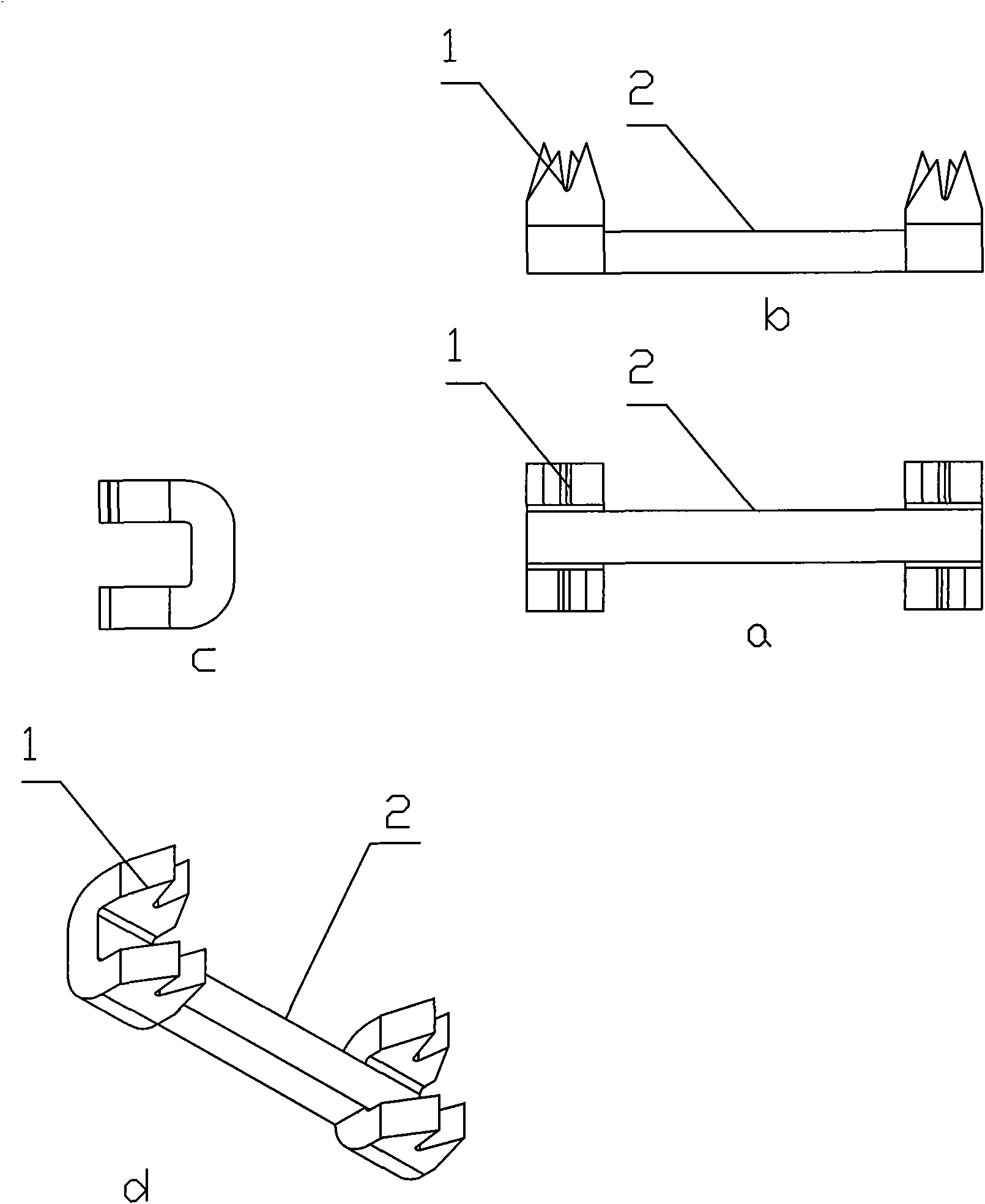
[0042] Such as image 3 As shown, a piercing connection conductor is provided, wherein the views a, b, c, d are respectively the main view, top view, side view and perspective view, and the difference from embodiment 1 is that in the piercing connection conductor of this embodiment , the piercing contacts at both ends are V-shaped.

Embodiment 3

[0044] Such as Figure 4 As shown, a piercing connection conductor is provided, wherein the views a, b, c, d are respectively the main view, top view, side view and perspective view, and the difference from embodiment 1 is that in the piercing connection conductor of this embodiment , the piercing contacts at both ends are W-shaped.


PUM


Abstract

The invention discloses a piercing connecting conductor. The piercing connecting conductor comprises a connecting conductor, wherein the connecting conductor is prepared from a conductive material; the two ends of the connecting conductor are respectively provided with at least one piercing contact; and the piercing contacts are electrically connected with the connecting conductor and used to pierce the insulation layer of a wire under the pressure. Two or more insulated wires can perform insulation joint or tapping without peeling off the insulation layers of the insulated wires in advance or cutting off the insulated wires; and meanwhile, the problems of the prior art such as low carrying current, low pressure resistance, narrow application area, less metal contact pieces and low piercing resistance can be solved simultaneously.

Description

technical field [0001] The invention relates to the field of electric power engineering, in particular to a piercing connecting conductor and a structure for connecting or tapping insulated wires. Background technique [0002] At present, there are mainly the following ways to realize the connection or branching of insulated wires: [0003] 1. Strip the insulation layer of the insulated wires in advance, then use the wires to directly wind and connect or tap the wires, and finally solder and wrap the insulation tape. [0004] 2 Cut off the insulated wires in advance and peel off the insulation layer of the insulated wires, and then use the metal connecting piece fixed in the box to connect or branch by screw compression. [0005] 3 Cut off the insulated wires in advance and peel off the insulation layer of the insulated wires, then use metal short tubes to squeeze and connect or tap, and finally wrap the insulation tape. [0006] 4. During the manufacturing process of insu...

Claims


Application Information

Patent Timeline
Patent Type & Authority Applications(China)
IPC IPC(8): H01R11/20H01R4/24H01R4/38
Inventor 王维金
Owner XIAN OCAME ELECTRIC
Why Eureka
Try Eureka