Source end network coding and alternated transmission-based relay cooperation method

A network coding, source-side technology, applied in transmission systems, digital transmission systems, electrical components, etc., can solve the problems of higher transmission efficiency and higher performance requirements of relay equipment, to improve throughput, improve efficiency, and save time slots Effect

Inactive Publication Date: 2011-01-26
UNIV OF SCI & TECH OF CHINA
View PDF1 Cites 18 Cited by
  • Summary
  • Abstract
  • Description
  • Claims
  • Application Information

AI Technical Summary

Problems solved by technology

This method also obtains space diversity gain. In the case of multiple relays, the transmission efficiency is 1 / 2, that is, one message is sent every two time slots on average. When the number of relays is large, it is much larger than the traditional relay transmission method. However, since the destination does not receive information for half of the time, its transmission efficiency cannot be higher, and it needs distributed space-time coding and synchronization on the relay, which requires higher performance of the relay equipment

Method used


Image

  • Source end network coding and alternated transmission-based relay cooperation method
  • Source end network coding and alternated transmission-based relay cooperation method
  • Source end network coding and alternated transmission-based relay cooperation method

Examples


Embodiment 1

[0024] Embodiment 1: Relay cooperation method based on source-end network coding and alternate transmission

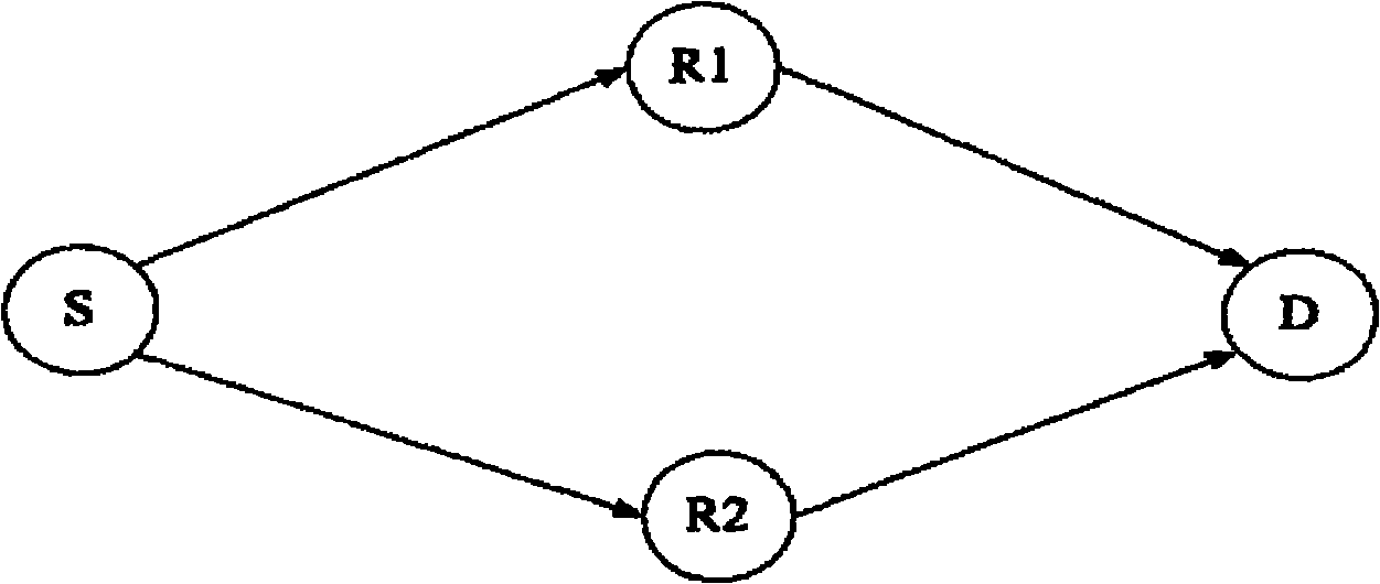
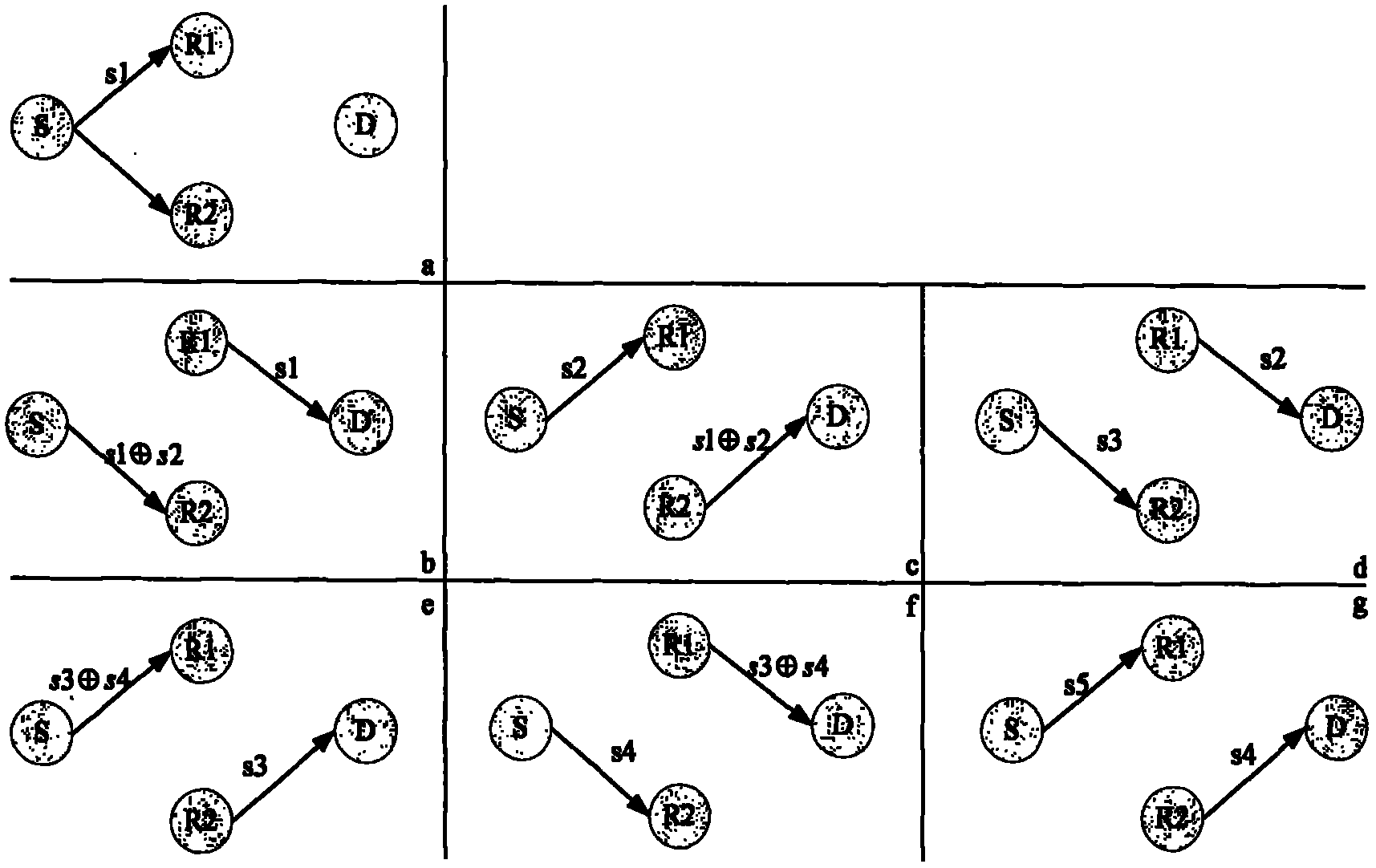
[0025] This embodiment takes figure 1 with figure 2 The schematic diagram of the wireless communication system using the relay cooperative transmission of the present invention is shown to introduce the specific implementation manner of the present invention. figure 1 A schematic diagram of the structural model of the relay cooperative transmission wireless communication system of the present invention is given. figure 2 It is a schematic diagram of the transmission process of the relay cooperative transmission system of the present invention based on this structural model.

[0026] Such as figure 1 As shown, the present invention is based on the relay cooperation method of source network coding and alternate transmission, and the entire relay cooperative communication system includes a source S, two relays, the first relay R1 and the second relay R2, and a destin...

Embodiment 2

[0046] Example 2: Performance and Simulation

[0047] Figure 4 The diversity multiplexing compromise performance curve G of the relay cooperation method based on source-end network coding and alternate transmission of the present invention, the diversity multiplexing compromise performance curve E of the traditional relay method, and the distributed space-time code transmission method are given The comparison between the diversity multiplexing trade-off performance curve F and the direct transmission diversity multiplexing trade-off performance curve H. from Figure 4 It can be seen that, under the same diversity gain, the relay cooperation method of the present invention has greater multiplexing gain than the traditional relay method and the distributed space-time code transmission method. In the case of two relays, the traditional relay method transmits one message every three time slots, and the transmission efficiency is 1 / 3, and the distributed space-time code transmis...


PUM


Abstract

The invention discloses a source end network coding and alternated transmission-based relay cooperation method, which is characterized in that: two relays are positioned outside the receiving radius of each other; a source end performs network coding on binary information sequences which are sent by the source end every three time slots; the two relays alternatively send the information in the adjacent time slots, the relay which sends the information in the last time slot receives the information in the present time slot, and the relay which receives the information in the last time slot sends the information in the present time slot; and when one relay receives the information sent by the source end in every time slot, the other relay forwards the information which is received and processed in the last time slot to a target end. Under the condition of not influencing cooperative diversity gain, the characteristics of two relay transmission models are fully utilized, more informationcan be transmitted within the same number of time slots, multiplexing loss in relay cooperative transmission is reduced, the transmission efficiency of the information is improved by 2/3, and both transmission performance and efficiency are considered in an actual relay cooperative communication system.

Description

technical field [0001] The invention belongs to the technical field of cooperative relay for wireless communication, and in particular relates to a method for cooperatively transmitting information by using relay in a wireless communication system. Background technique [0002] The performance of the wireless communication system is mainly restricted by the wireless channel. Wireless channels are not as fixed and predictable as wired channels, but have great randomness. The propagation path between the transmitter and the receiver is often very complicated, from simple line-of-sight propagation to encountering various complex terrains, such as buildings, mountains, leaves, etc., which makes the transmitted signal experience severe channel fading, thus As a result, the signal-to-noise ratio of the signal received by the receiver is low, and the error probability is high. In order to improve bit error performance, "Proceedings.2001IEEEInternational Symposium on Information T...

Claims


Application Information

Patent Timeline
Patent Type & Authority Applications(China)
IPC IPC(8): H04L1/00H04L1/06
Inventor 肖爱民李辉
Owner UNIV OF SCI & TECH OF CHINA
Why Eureka
Try Eureka