Chip suction drill

A chip and drill bit technology, which is applied in the direction of drill repair, drill accessories, drilling/drilling equipment, etc., can solve the problems of not being able to obtain chip attraction, not being able to suck chips smoothly, and difficult air flow

Active Publication Date: 2011-01-26
OSG
View PDF0 Cites 13 Cited by
  • Summary
  • Abstract
  • Description
  • Claims
  • Application Information

AI Technical Summary

Problems solved by technology

In addition, since the helical groove is continuously provided in the axial direction on the cutting edge groove for forming the cutting edge, air is introduced from the tip side of the tool under the helical groove, and there is a chip suction passage that only sucks in air. The problem that chips cannot be sucked

Method used


Image

  • Chip suction drill
  • Chip suction drill
  • Chip suction drill

Examples


Embodiment

[0046] Hereinafter, embodiments of the present invention will be described in detail with reference to the drawings.

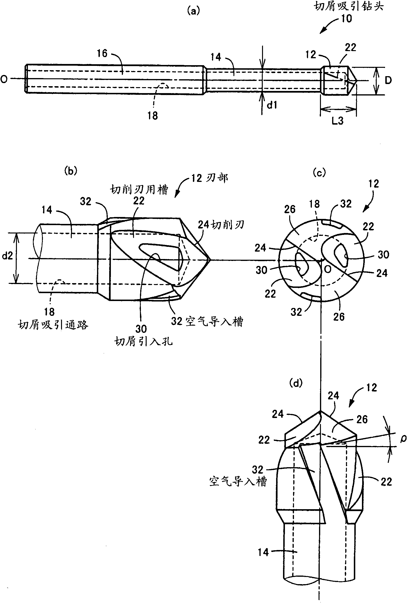
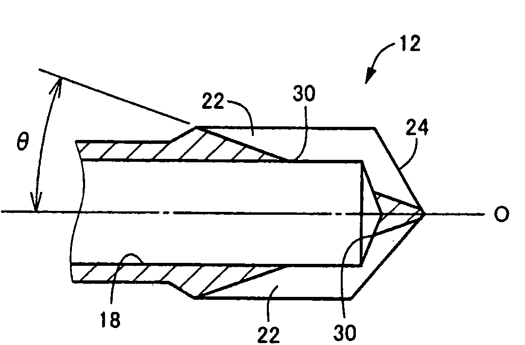
[0047] figure 1 It is a diagram showing a chip suction drill 10 as an embodiment of the present invention, (a) is a schematic front view seen from a direction perpendicular to the axis O, and (b) is a cutting edge portion 12 at the tip (c) is an end view viewed from the right side of (b), that is, viewed from the front end side, (d) is an illustration viewed from the bottom of (c), which is the same as (b) ) compared to that seen when viewed from a direction that is 90° out of phase around the axis O. The chip attracting drill 10 is made of cemented carbide, and at the same time, it is continuously and integrally equipped on the axis O: a cutting edge 12 having the same diameter as the drill diameter D, which is smaller than the cutting edge 12 and has a certain diameter. The head 14 of d1, and the drill shank 16 having the same diameter size as the cutting ...


PUM


Abstract

A chip suction drill (10) performs a hole making process to a material to be ground (42) such as a casting using a cutting blade (24). A chip generated is suctioned in a chip suction path (18) from a chip intaking hole (30) formed in a cutting blade groove (22) and ejected to a shank (16) side. In this case, since an air introduction groove (32) is provided in the outer periphery surface of a blade (12), air is excellently introduced into the leading end of a tool at which the chip is generated by the cutting blade (24) and the air introduced into the leading end of the tool upon the suction of air by the chip suction path (18) is excellently suctioned in the chip intaking hole (30) together with the chip. Particularly, since only one chip suction path (18) is provided in the tool, its cross section area can be sufficiently secured and the chip intaking hole (30) can be enlarged along with the enlargement of the chip suction path (18). Thus, the generation of chip packing can be suppressed and excellent chip suction performance can be obtained.

Description

technical field [0001] The present invention relates to a drill, and more particularly, to a chip suction drill for forcibly sucking and discharging chips for the purpose of preventing environmental pollution and simplifying cleaning work. Background technique [0002] In the prior art, a chip attracting drill has been proposed which has: (a) a groove for cutting edge is formed on the outer peripheral surface, and an edge of the groove for cutting edge is opened on the tool front end side; A cutting edge for drilling is provided, and (b) a chip suction path of a cutting introduction hole provided along the axis inside the tool and simultaneously formed on the groove for the cutting edge; Rotate and drive one side around the axis to advance toward the front end of the tool, and perform drilling with the cutting edge. At the same time, the chips generated during the drilling process are sucked from the chip introduction hole into the chip suction passage, and flow toward the d...

Claims


Application Information

Patent Timeline
IPC IPC(8): B23B51/06
CPCB23B51/06B23B2270/62
Inventor 大桥诚司伊藤实朗那温布阿卡乌高桥秀通
Owner OSG
Why Eureka
Try Eureka