Exhaust manifold of an internal combustion engine
A technology of exhaust manifold and exhaust pipe, which is used in exhaust devices, combustion engines, mechanical equipment, etc. to achieve the effect of short heating time
- Summary
- Abstract
- Description
- Claims
- Application Information
AI Technical Summary
Problems solved by technology
Method used
Image
Examples
Embodiment Construction
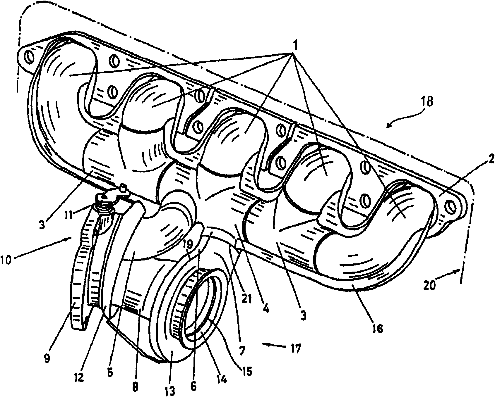
[0025] figure 1 Shown is a perspective view of an exhaust manifold 18 flange mounted on an internal combustion engine 20 (indicated by dotted lines) and connected to an exhaust turbocharger (not all shown) On one of the turbine housings 17. The presentation of said part is sufficient for the following explanation of the principle of the invention, wherein it should be emphasized that the exhaust-gas turbocharger of course has all other conventional design features, but these features are not described in figure 1 reproduced in , to simplify the illustration.
[0026] according to figure 1 In the illustrated embodiment, the internal combustion engine 20 has five exhaust manifold bends 1 which lead to the associated T-shaped exhaust manifold 3 and are connected thereto and lead into a manifold part 4 , the manifold part is also designed as a T-shaped exhaust pipe, as in figure 1 are shown in detail in the graphical presentation.
[0027] As stated, figure 1 Only one exempl...
PUM
 Abstract
Description
Claims
Application Information
 - R&D
- Intellectual Property
- Life Sciences
- Materials
- Tech Scout
- Unparalleled Data Quality
- Higher Quality Content
- 60% Fewer Hallucinations
Browse by: Latest US Patents, China's latest patents, Technical Efficacy Thesaurus, Application Domain, Technology Topic, Popular Technical Reports.
© 2025 PatSnap. All rights reserved.Legal|Privacy policy|Modern Slavery Act Transparency Statement|Sitemap|About US| Contact US: help@patsnap.com


