Tip-extension type deep hole boring cutter rod

A telescopic and boring tool bar technology, which is applied in the direction of boring bars, tool holder accessories, and tools used in lathes, etc., can solve the problems of inability to perform cutting processing, affecting the processing of long-axis parts, and large length-to-diameter ratio of the tool bar. , to achieve the effect of low manufacturing cost, stable processing state and guaranteed rigidity

Active Publication Date: 2011-02-02
AECC AVIATION POWER CO LTD
View PDF0 Cites 30 Cited by
  • Summary
  • Abstract
  • Description
  • Claims
  • Application Information

AI Technical Summary

Problems solved by technology

[0003] If a fixed tool bar is used for processing, the tip of the tool should enter from the small diameter at the end of the part, and then radially feed to process the large diameter in the middle. The diameter of the tool bar mus

Method used


Image

  • Tip-extension type deep hole boring cutter rod
  • Tip-extension type deep hole boring cutter rod
  • Tip-extension type deep hole boring cutter rod

Examples


Embodiment Construction

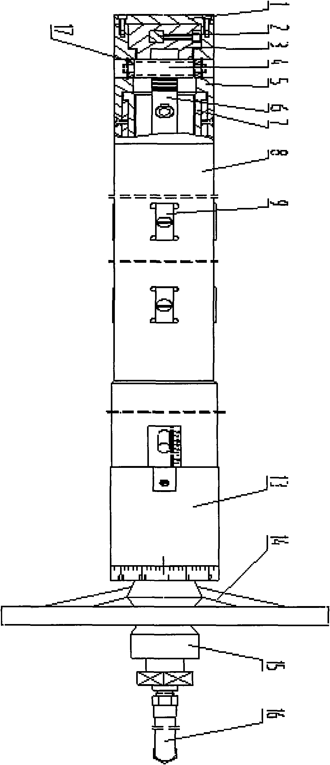
[0054] This embodiment is a telescopic deep-hole boring tool bar for machining a deep hole of a long-axis part, including an outer tool bar system, an inner transmission system and a cooling system.

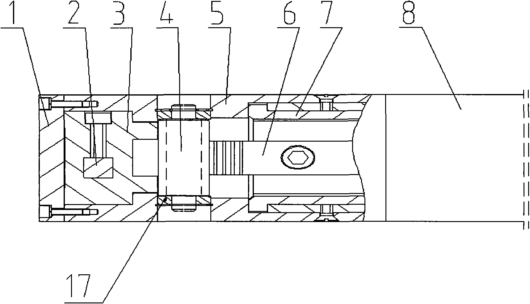
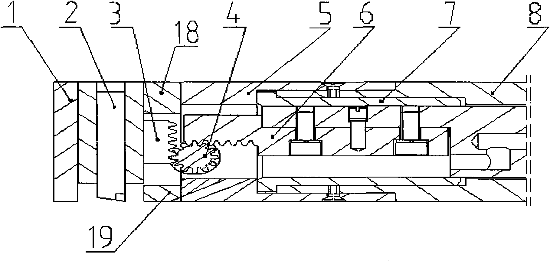
[0055] The outer knife bar system includes a gland 1, a gear mounting seat 5, an outer knife bar 8, a first copper sleeve 7, a second copper sleeve 12, a guide block 9, a bearing seat 13, a first baffle plate 18 and a second baffle plate 19 .

[0056] Gland 1 is a circular plate, the outer diameter of which is the same as that of outer cutter bar 8; two groups of connection holes are symmetrically distributed on the outer edge of gland 1, and there are two positioning pin holes on the center line of gland 1, and the two Two positioning pin holes are symmetrically distributed on the outer edge of the gland 1; the centers of the connecting holes and the positioning pin holes are on the same line, and the positioning pin holes are located between the connecting holes.

[0057] as a...


PUM


Abstract

The invention relates to a tip-extension type deep hole boring cutter rod. A cutter seat (3) is positioned in a cavity between a press cover (1) and a gear installing seat (5), and a screw rod (11) connected with one end of a core shaft (10); a rack (6) is installed in a slot on one end of the core shaft (10); one inner edge of a cutter installing hole needs to be coincide with the symmetric center surface of double-row teeth; a cutter (2) is positioned in the cutter installing hole, and a tip is positioned on a center line of a processed hole; and gears (4) are respectively meshed with the double-row teeth of the rack and the cutter seat. The screw rod is rotated by rotating a handle (14) on the screw rod (11) to drive the core shaft (10) to move, and then the cutter tip is extended by the transmission among a thread pair, the rack, gears and the rack. When retracting, the tip enters the end part of an inner hole of a part; and when the tip extends out, the middle of the part is processed. By adopting a guiding block (9), the rigidity of the cutter rod is ensured, and the cutter rod is provided with axial scales and circumferential scales. The tip-extension type deep hole boring cutter rod is suitable for processing deep holes on both ends of a long-shaft part, wherein the deep holes have small inner diameters at two ends, large inner diameters in the middles and larger difference of diameter sizes.

Description

1. Technical field [0001] The invention relates to a tool for mechanical processing, in particular to a telescopic deep-hole boring tool bar with a tool tip. 2. Background technology [0002] For the tools for deep hole machining of long-axis parts with small diameters at both ends, large diameters in the middle, and large diameter differences, due to the confidentiality of foreign professional tool companies, their technology cannot be obtained at present. According to research, there is currently no boring tool bar capable of processing such parts in China. [0003] If a fixed tool bar is used for processing, the tip of the tool should enter from the small diameter at the end of the part, and then radially feed to process the large diameter in the middle. The diameter of the tool bar must be much smaller than the diameter of the end of the part, resulting in a large length-diameter ratio of the tool bar. Vibration is generated, and cutting processing cannot be performed, ...

Claims


Application Information

Patent Timeline
IPC IPC(8): B23B29/12B23B29/02B23B27/10
Inventor 李海燕陈贵林潘继红赵建武沈军秦锋王文成刘丽娟
Owner AECC AVIATION POWER CO LTD
Why Eureka
Try Eureka