Sunk well structure and construction method thereof

A caisson and well body technology, which is applied in infrastructure engineering, caisson, construction, etc., can solve the problems of difficult soil removal, large frontal resistance, large bending moment, etc., and achieves easy construction operation and positioning control. A small number of effects with a simple structure

Inactive Publication Date: 2011-02-02
ZHONGTIE MAJOR BRIDGE RECONNAISSANCE & DESIGN INST
View PDF3 Cites 12 Cited by
  • Summary
  • Abstract
  • Description
  • Claims
  • Application Information

AI Technical Summary

Problems solved by technology

For rectangular caissons, the bending rigidity is large, and under the action of bending moment, the overall force of caissons is better; however, the well holes of rectangular caissons are generally arranged in a determinant, and under the action of horizontal earth pressure, vertical and horizontal partition walls form wells. The fulcrum of the wall, the well wall is a multi-point support beam in the plane, the bending moment is large, and the force is poor; and the determinant is a non-centrosymmetric structure, which is prone to torsion and difficult to correct during the sinking
[0004] For the circular cross-section, it is a center-symmetrical structure, which is easy to locate in the sinking; but if the circular cross-section caisson wells are arranged in a determinant, there are also defects of the rectangular cross-section caissons; Although the force is better, due to the large number of holes, there is a large area of ​​solids between the round holes in the plane. During the sinking process of the caisson, the soil under the solids is difficult to remove, resulting in a large frontal resistance, and the sinking It is difficult to sink; and due to the large physical area, the amount of concrete in the shaft is large
[0005] Therefore, the current caisson foundation structure has certain defects in economy, construction convenience or force rationality

Method used


Image

  • Sunk well structure and construction method thereof
  • Sunk well structure and construction method thereof
  • Sunk well structure and construction method thereof

Examples


Embodiment Construction

[0022] The present invention will be further described below in conjunction with the accompanying drawings and specific embodiments, so that those skilled in the art can better understand the present invention and implement it, but the examples given are not intended to limit the present invention.

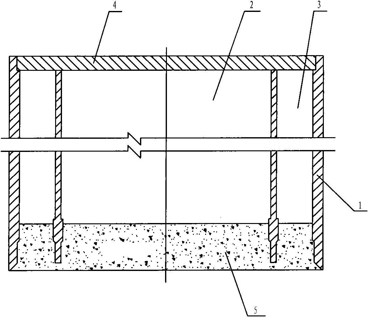
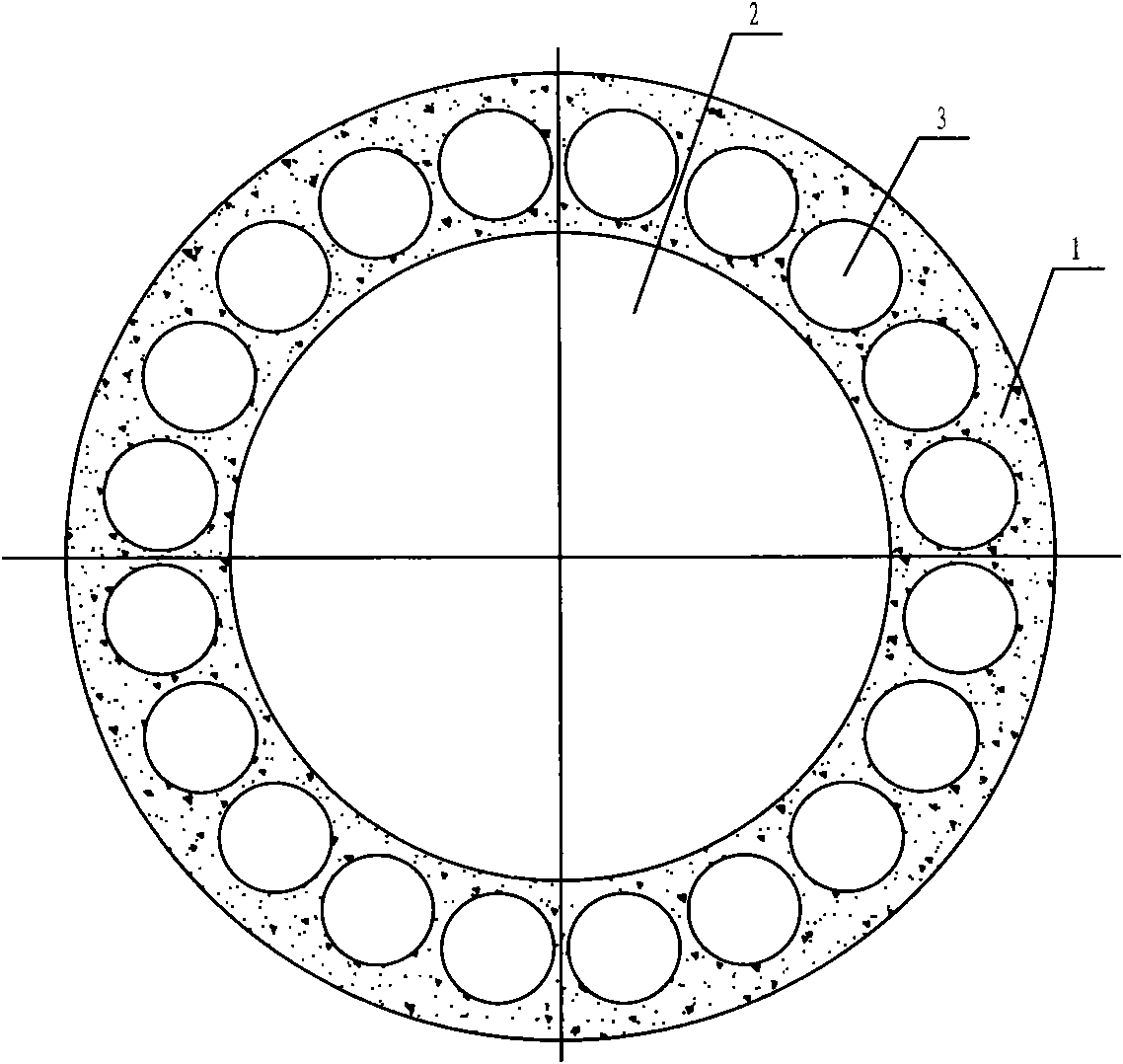
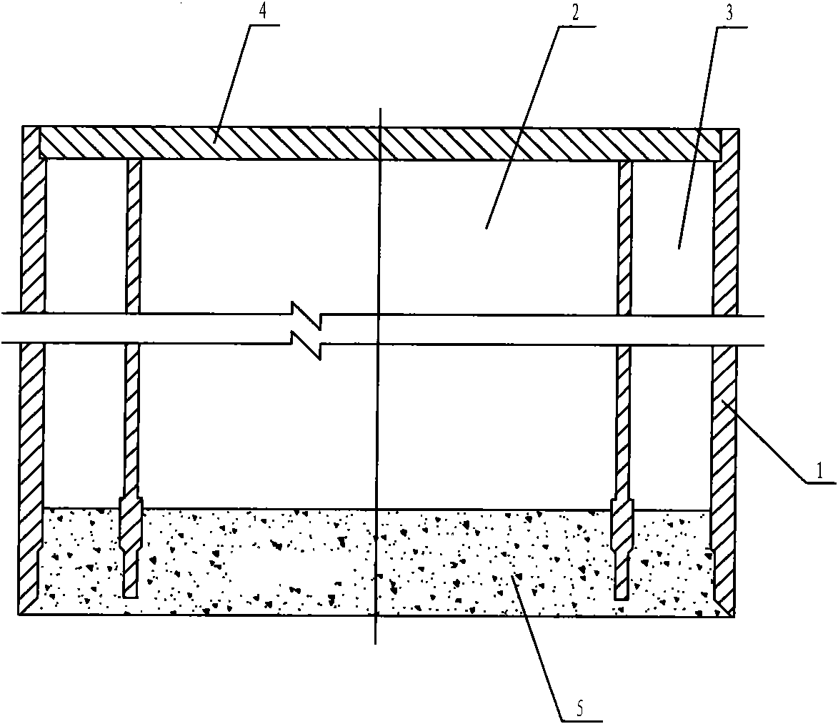
[0023] Such as figure 1 and figure 2 As shown, the caisson structure of the present invention includes a well body, the outer contour of the well body cross section is circular, the center is provided with a central hole, the well body around the central hole forms a well wall, and the well wall is provided with a plurality of The holes are parallel to the circular holes, and the circular holes are symmetrically distributed around the axis of the well body. The well body can be divided into multiple sections to facilitate construction. The lowermost section of the well body is a steel shell concrete structure, and the bottom of the lowermost section of the well body is also pro...


PUM


Abstract

The invention discloses a sunk well structure, comprising a well body which is round in the outer profile of the section and provided with a central hole in the center, a well wall is formed on the well body on the periphery of the central hole and provided with a plurality of round holes parallel to the central hole, and the round holes are symmetrically distributed with the axis of the well body as a center. The sunk well structure of the invention has the advantages of simple structure, fewer hole number and reasonable stress, and the section of the sunk well is in a centrosymmetry structure and the well holes comprises big holes and small hole, therefore, construction operation and positioning control are convenient when sinking.

Description

technical field [0001] The invention relates to foundations of large bridges, including deep water foundations and anchorage foundations of suspension bridges. Background technique [0002] With the development of domestic bridge construction, large-scale bridge foundations continue to appear. At present, the common bridge foundations mainly include pile foundations, enlarged foundations, and caisson foundations. Expanded foundations are greatly affected by geological conditions, and are less used in thicker covering layers or deep water; pile foundations are the most widely used, but for large bridge foundations, the scale of pile foundations is larger and the engineering cost is higher; while the stiffness of caisson foundations Large scale, small scale, and relatively short construction period, there is a large room for development in bridge construction. [0003] The current caisson foundation cross-sections mainly include circular, rectangular and round-end types, and...

Claims


Application Information

Patent Timeline
Patent Type & Authority Applications(China)
IPC IPC(8): E02D23/08E02D27/18
Inventor 高宗余杨进朱旭初杨光武李明华杨灿文罗昕刘岩蒋益明张德平
Owner ZHONGTIE MAJOR BRIDGE RECONNAISSANCE & DESIGN INST
Why Eureka
Try Eureka