Time sequence control circuit and control method thereof

A timing control circuit and control circuit technology, applied in electrical program control, program control in sequence/logic controllers, etc., can solve the problems of complex process, high chip manufacturing cost, permanent chip damage, etc., and achieve simple process, The effect of low manufacturing cost and simple structure

Active Publication Date: 2011-02-02
珠海市鑫和电器有限公司
View PDF6 Cites 32 Cited by
  • Summary
  • Abstract
  • Description
  • Claims
  • Application Information

AI Technical Summary

Problems solved by technology

With the development of chips, the power supply structure is also diversified based on considerations of reliability, stability, and cost; under this development trend, the electronic chips used in equipment are also diverse. The requirements are becoming more and more complex. For equipment powered by multiple power supplies, different chips in the equipment or different modules of the same chip have strict requirements on the power-on sequence of multiple power supplies, and some even have certain requirements on the power-off sequence. If the power-on or power-off sequence is improper, it will not only affect the reliability of the chip and equipment, but may even cause permanent damage to the chip
[0003] At present, most of the commonly used timing control circuits are implemented by a special timing control chip. Although the timing control chip can control the timing of power-on and power-off, the chip has high manufacturing costs and complicated processes, and is not suitable for large areas. Promotion

Method used


Image

  • Time sequence control circuit and control method thereof
  • Time sequence control circuit and control method thereof
  • Time sequence control circuit and control method thereof

Examples


Embodiment Construction

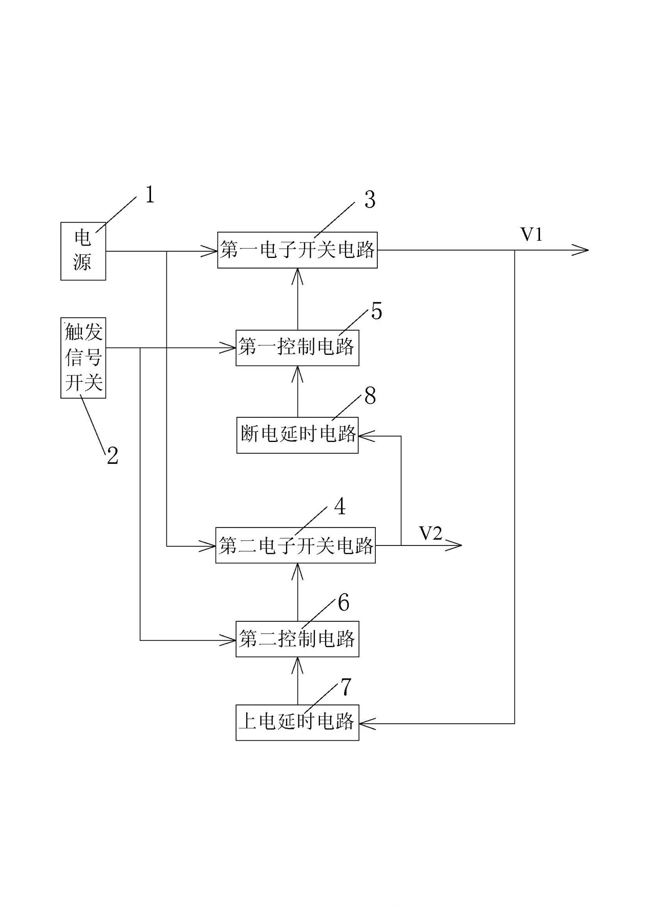
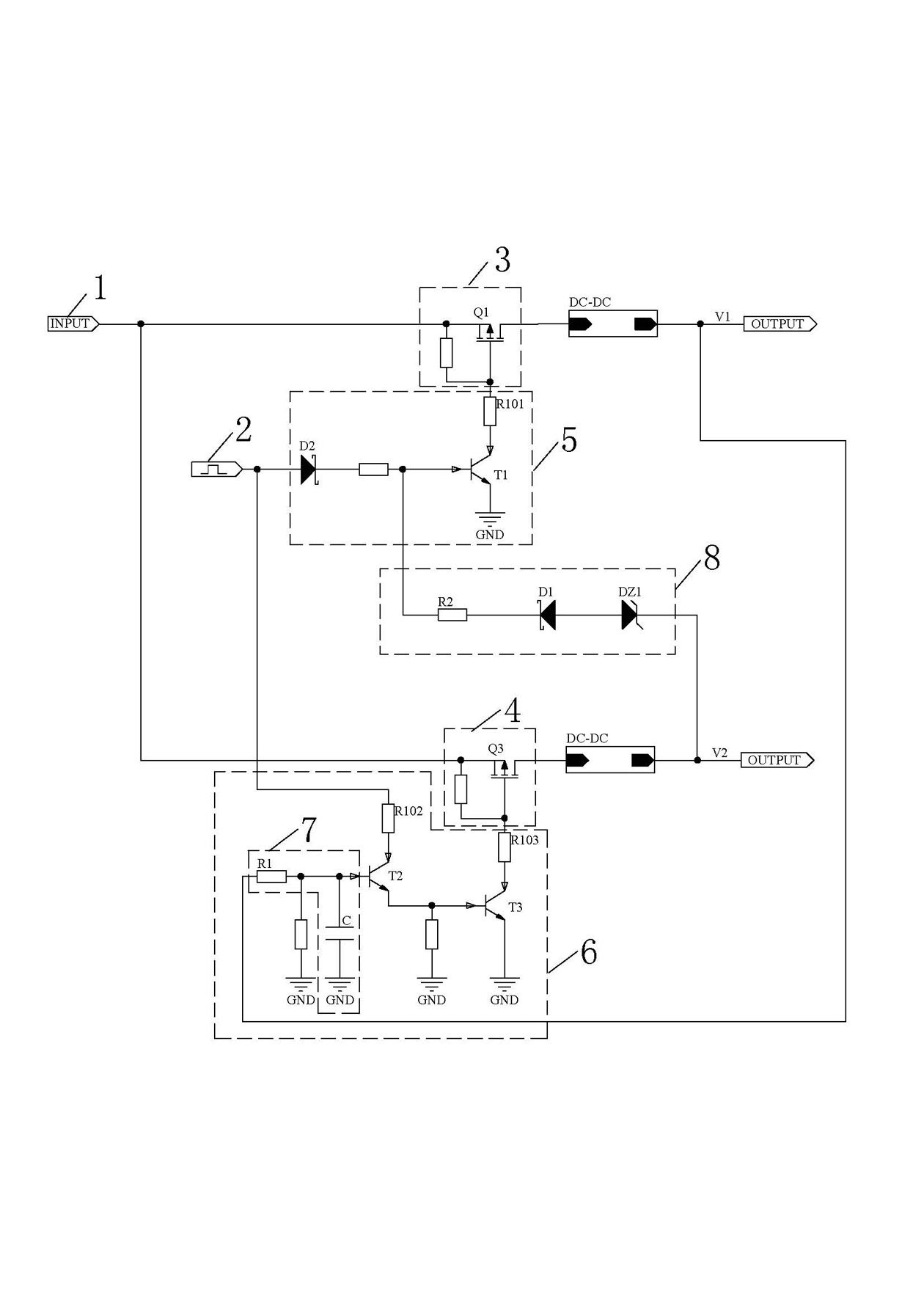
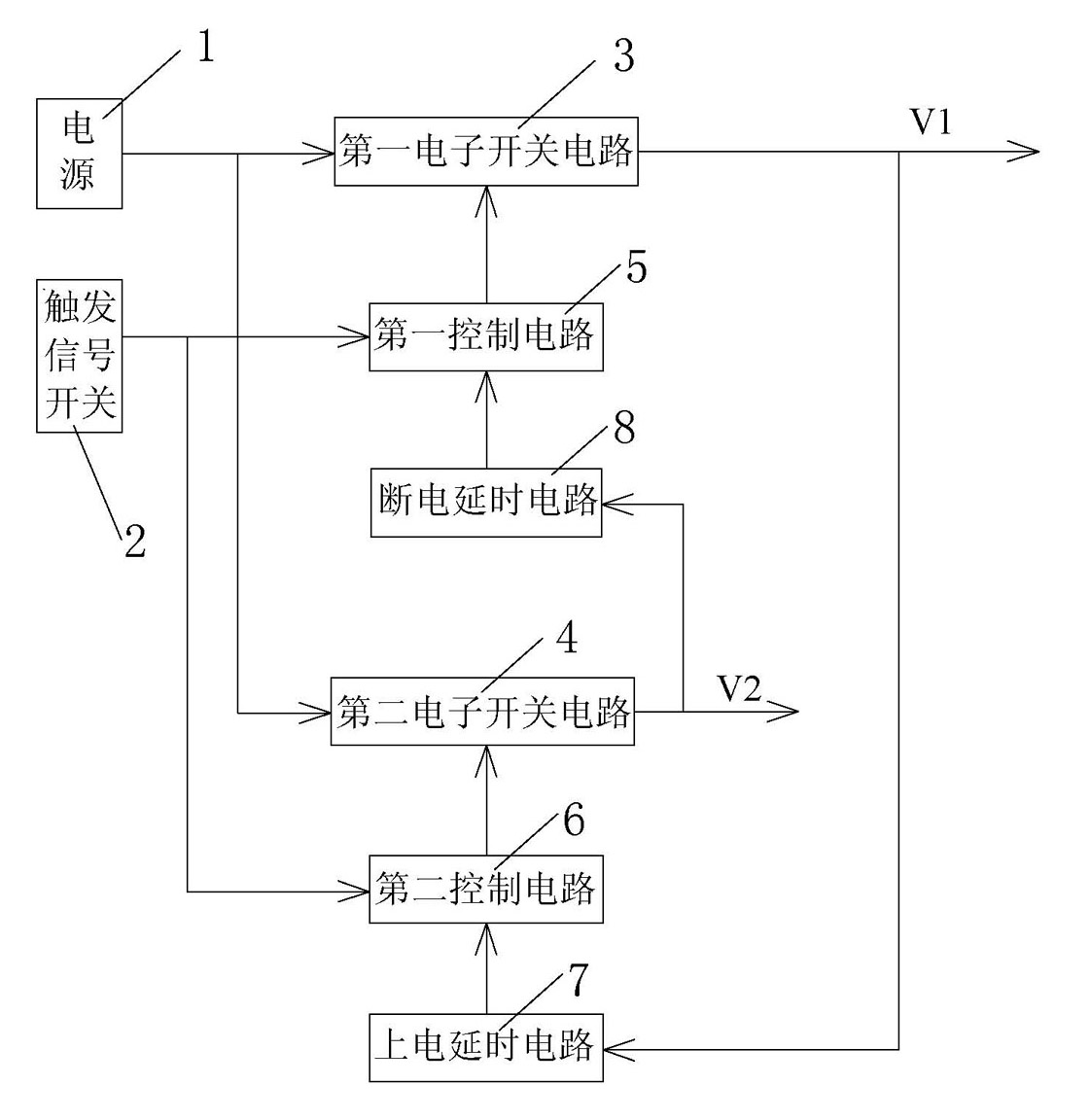
[0022] refer to figure 1 , a timing control circuit of the present invention, comprising a power supply 1, a trigger signal switch 2, a first electronic switch circuit 3 connected in series between the power supply 1 and the first voltage output terminal V1, and connected in series between the power supply 1 and the second voltage output terminal The second electronic switch circuit 4 between V2, the first control circuit 5 connected between the trigger signal switch 2 and the first electronic switch circuit 3, the first control circuit 5 connected between the trigger signal switch 2 and the second electronic switch circuit 4 Two control circuits 6, RC power-on delay circuit 7 and power-off delay circuit 8; wherein, the RC power-on delay circuit 7 is connected between the first voltage output terminal V1 and the input terminal of the second control circuit 6 , the power-off delay circuit 8 is connected between the second voltage output terminal V2 and the input terminal of the...


PUM


Abstract

The invention discloses a time sequence control circuit, which comprises a power supply, a trigger signal switch, a first electronic switching circuit, a second electronic switching circuit, a first control circuit, a second control circuit, a Resistor Capacitor (RC) power-on delay circuit and a power-off relay circuit, wherein the first electronic switching circuit is connected in series between the power supply and a first voltage output end; the second electronic switching circuit is connected in series between the power supply and a second voltage output end; the first control circuit is connected between the trigger signal switch and the first electronic switching circuit; the second control circuit is connected between the trigger signal switch and the second electronic switching circuit; the Resistor Capacitor (RC) power-on delay circuit is connected between the first voltage output end and an input end of the second control circuit; and the power-off relay circuit is connected between the second voltage output end and an input end of the first control circuit. The time sequence control circuit can simultaneously control power-on time sequences and power-off time sequences of different power supplies of an internal chip of equipment, increase the reliability of the running of the equipment and the chip, and extend the service life of the equipment and the chip; besides, the time sequence control circuit has the advantages of simple structure, low manufacturing cost, simple process and suitability for large-scale popularization.

Description

technical field [0001] The invention relates to the technical field of intelligent control of power supplies, in particular to a sequence control circuit and a control method thereof. Background technique [0002] With the rapid development of electronic technology, DSP (digital signal processor), CPU (central processing unit), large-scale integrated circuits, etc. are widely used in communication, automatic control, aerospace, medical, household appliances and other fields. With the development of chips, the power supply structure is also diversified based on considerations of reliability, stability, and cost; under this development trend, the electronic chips used in equipment are also diverse. The requirements are becoming more and more complex. For equipment powered by multiple power supplies, different chips in the equipment or different modules of the same chip have strict requirements on the power-on sequence of multiple power supplies, and some even have certain requ...

Claims


Application Information

Patent Timeline
Patent Type & Authority Applications(China)
IPC IPC(8): G05B19/04
Inventor 岳国宾
Owner 珠海市鑫和电器有限公司
Why Eureka
Try Eureka