
Strain tower with shape like Chinese character 'gan' of compact transmission line

A transmission line and dry-shaped technology, applied in the direction of towers, electrical components, building types, etc., can solve the problems of low air gap of the lower phase jumper, large amount of tree felling, insufficient clearance of supports, etc., and achieve a small amount of earth and stone extraction , reduce tree felling, economically reasonable effect

Active Publication Date: 2012-06-06
CENT SOUTHERN CHINA ELECTRIC POWER DESIGN INST CHINA POWER ENG CONSULTING GROUP CORP
View PDF3 Cites 0 Cited by
  • Summary
  • Abstract
  • Description
  • Claims
  • Application Information

AI Technical Summary

Problems solved by technology

However, the type of tension tower used basically follows the original design scheme. In actual engineering applications, due to the air gap problem of the lower phase jumper, it is often necessary to cut down trees or excavate earth and rocks. At the same time, the existing compact tension tower The tower also has the disadvantages of high height, complex structure, and high cost of the body.
[0003] Specifically, the existing compact line strain towers have the following disadvantages: ① Higher height: the height range of existing compact strain towers is generally 24m to 42m
② High cost of the main body: the structure of the existing compact tension tower is complex, and the cost of the main body is high
③. The air gap of the lower phase jumper of the existing compact tension tower is low, and the amount of tree felling is large
⑤. Large potential safety hazard: In extreme cases, the existing compact tension tower may have insufficient clearance between the upper phase wire tension string equalizing ring and the lower phase jumper bracket, which may easily cause potential safety hazards

Method used


Image

  • Strain tower with shape like Chinese character 'gan' of compact transmission line
  • Strain tower with shape like Chinese character 'gan' of compact transmission line
  • Strain tower with shape like Chinese character 'gan' of compact transmission line

Examples


Embodiment Construction

[0025] The implementation of the present invention will be described in detail below in conjunction with the accompanying drawings, but they do not constitute a limitation to the present invention, and are only examples. At the same time, the advantages of the present invention will become clearer and easier to understand.

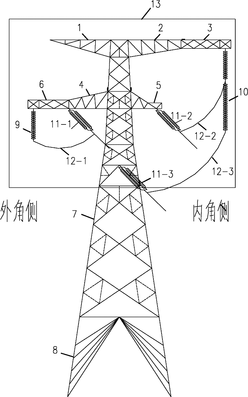
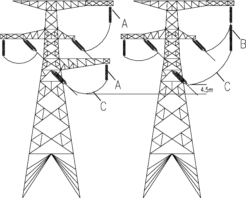
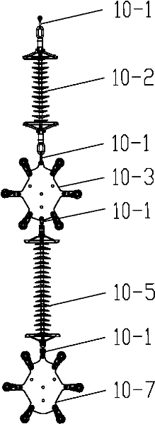
[0026] Referring to the accompanying drawings, it can be seen that the compact dry-type tension tower of the transmission line of the present invention includes tower legs 8, tower body 7, tower head 13, conductor tension strings 11, ordinary jumper strings 9 and interphase combined jumper strings 10 , the upper end of the tower head 13 is provided with a ground wire bracket and a joint jumper wire bracket 3, and the ground wire bracket includes an outer corner side ground wire bracket 1 and an inner corner side ground wire bracket 2, and the inner corner side ground wire bracket 2 is located on the outer corner side Between the ground wire support 1 and t...


PUM


Abstract

The invention relates to a strain tower with a shape like a Chinese character 'gan' of a compact transmission line, comprising tower legs (8), a tower body (7), a tower head (13), a conducting wire strain string (11), a common jumper string (9) and a united jumper string (10), wherein a second conducting wire strain string (11-2) is connected with an upper-phase jumper suspension wire string (10-3) of the interphase united jumper string (10) by a second jumper (12-2), and a third conducting wire strain string (11-3) is connected with a lower-phase jumper suspension wire string (10-7) of the interphase united jumper string (10) by a third jumper (12-3). The invention has simple structure, increases the earth height of the lower-phase jumper, solves the detects of higher calling height, complicated structure and high self cost of the traditional compact type strain tower structure and reduces tree felling and earth and rock extraction. The compact ultra-high-voltage transmission line has more advanced technology, is more reasonable in economy and more environment-friendly in ecology.

Description

technical field [0001] The invention relates to an iron tower of an overhead power transmission line, more specifically, it is a compact dry-shaped tension tower of a power transmission line. Background technique [0002] With the continuous development of my country's ultra-high voltage power grid, new issues and new requirements have been put forward for the construction of transmission lines. my country's compact lines were initially only used in plain areas such as North China. Because of their advantages such as large transmission capacity and narrow line corridors, they have been widely promoted across the country in recent years. However, the type of tension tower used basically follows the original design scheme. In practical engineering applications, due to the air gap problem of the lower phase jumper, it is often necessary to cut down trees or excavate earth and rocks. At the same time, the existing compact tension tower The tower also has the disadvantages of hi...

Claims


Application Information

Patent Timeline
Patent Type & Authority Patents(China)
IPC IPC(8): H02G7/00H02G7/20H02G7/02E04H12/22
Inventor 鲁景星刘文勋江卫华李翔赵全江黄欲成李健马凌康励于欲陈媛
Owner CENT SOUTHERN CHINA ELECTRIC POWER DESIGN INST CHINA POWER ENG CONSULTING GROUP CORP
Learn More