
Five-phase switch magnetic resistance motor

A technology of reluctance motor and phase switch, which is applied in the direction of electrical components, electromechanical devices, magnetic circuit static parts, etc., can solve the problems of low working frequency, unstable rotation, low efficiency, etc., and achieve high working frequency and high rotation Smooth, efficient results

Inactive Publication Date: 2011-02-02
NINGBO INST OF TECH ZHEJIANG UNIV ZHEJIANG
View PDF3 Cites 10 Cited by
  • Summary
  • Abstract
  • Description
  • Claims
  • Application Information

AI Technical Summary

Problems solved by technology

[0004] First, the traditional five-phase switched reluctance motor is a concentrated winding, there is no mutual inductance between the phase windings, and the magnetic potential does not superimpose during operation
And only 1.5 windings participate in the operation on average during operation, so that the performance-to-volume ratio of the motor is not high, that is, the torque of the motor with the same volume is small
[0005] Second, traditional five-phase switched reluctance motors usually use concentrated windings, the magnetic potential is not superimposed during operation, the current flowing through the windings during operation is relatively large, the copper consumption is high, and the efficiency is low
[0006] Third, the traditional five-phase switched reluctance motor operates at a low frequency at a low speed, and the rotation is not stable

Method used


Image

  • Five-phase switch magnetic resistance motor
  • Five-phase switch magnetic resistance motor
  • Five-phase switch magnetic resistance motor

Examples


Embodiment Construction

[0018] The present invention will be further described below in conjunction with the accompanying drawings and specific embodiments.

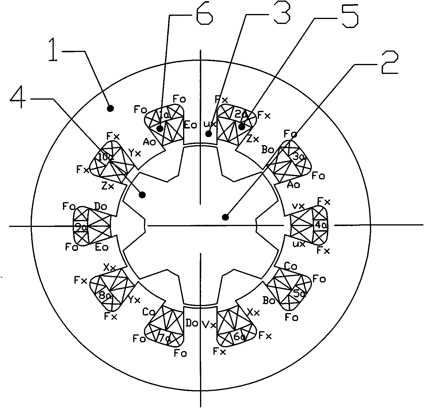
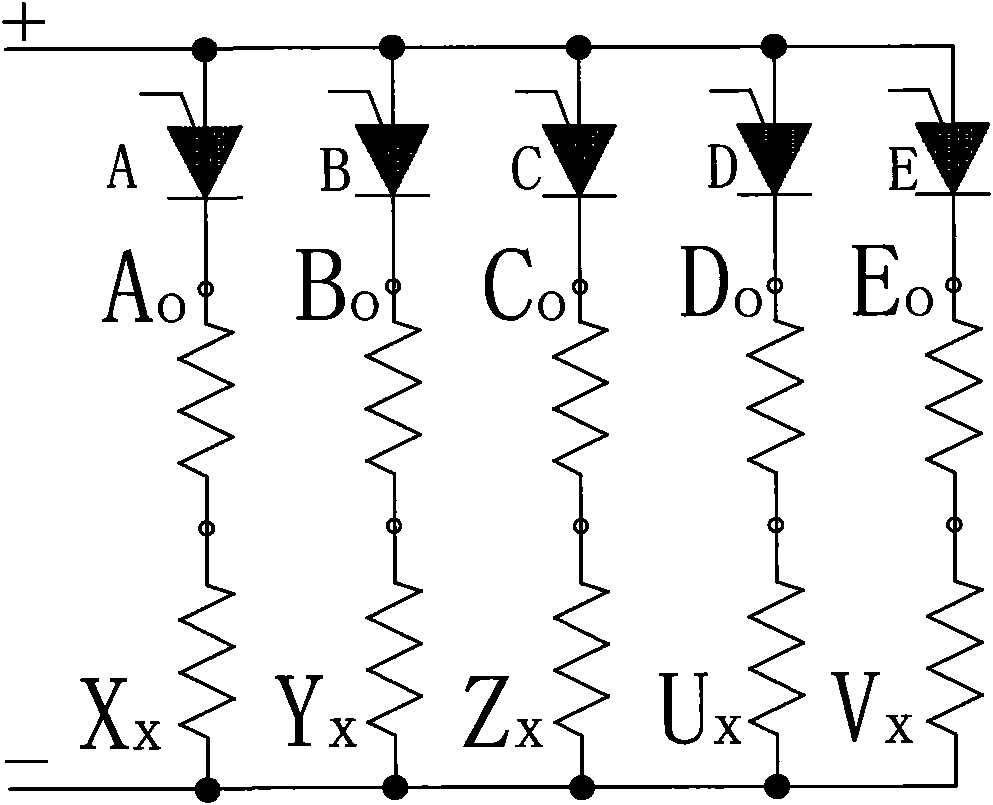
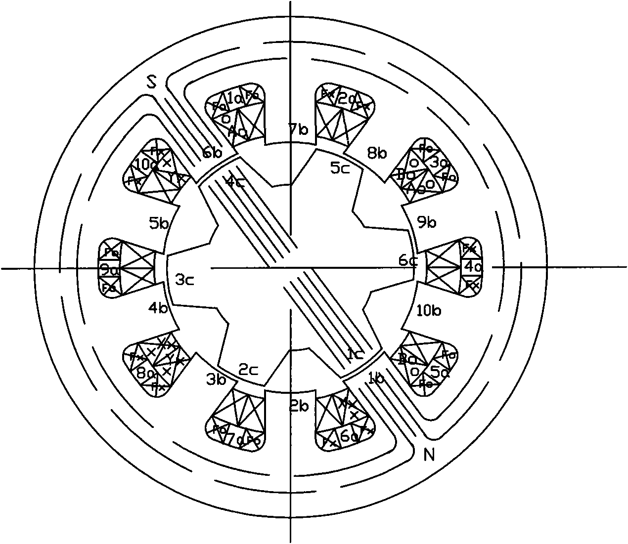
[0019] Such as figure 1 As shown, the present invention provides a five-phase switched reluctance motor, which includes a stator 1, a rotor 2, and a stator winding 5. Stator teeth 3 are uniformly distributed on the inner surface of the stator 1, and between every two adjacent stator teeth A stator slot 6 is formed between them, rotor teeth 4 are evenly distributed on the outer surface of the rotor 2, the stator winding 5 is composed of five-phase windings, the number of teeth of the stator teeth 3 is 10i, and the number of teeth of the rotor teeth 4 is 10i-4 or 10i-6, wherein i is an integer greater than 0, the stator winding 5 is a double-layer winding, and the five-phase windings are evenly distributed in the stator 1 . The windings of each phase are composed of two coils in series, and the two coils of each phase are symmetrically distribut...


PUM


Abstract

The invention relates to a five-phase switch magnetic resistance motor, comprising a stator, a rotor and stator windings, wherein the inner circular surface of the stator is uniformly distributed with stator teeth; the outer surface of the rotor is uniformly distributed with rotor teeth; the stator windings comprise five phases of windings; the number of teeth of the stator is 10i, and the number of teeth of the rotor is 10i-4 or 10i-6, wherein i is an integer more than 0; the stator windings are dual-layer windings and are uniformly distributed in the stator; each phase of winding is formed by in-series connection of two coils which are symmetrically distributed in the stator; and the pitch of the coils is 3. The five-phase switch magnetic resistance motor adopting the structure has the advantages of higher performance-volume ratio, lower copper consumption, higher efficiency and smooth running at low rotating speed.

Description

technical field [0001] The invention relates to the field of motors, in particular to a five-phase switched reluctance motor. Background technique [0002] The traditional switched reluctance motor has a stator and rotor with a salient pole structure. Through a simple operating drive circuit, the coils of each phase of the stator winding are energized in a certain sequence to generate pulsating magnetic flux. The rotor is subjected to magnetic torque in the pulsating magnetic field, and thus rotates. Since there are no windings and permanent magnets on the rotor, the motor has a simple structure and reliable operation, and can achieve wide-range speed regulation by adjusting the on-off frequency of the drive circuit for each phase coil. Therefore, it can be widely used in various occasions requiring speed regulation and high efficiency. [0003] But the traditional five-phase switched reluctance motor still has the following deficiencies: [0004] First, the traditional f...

Claims


Application Information

Patent Timeline
Patent Type & Authority Applications(China)
IPC IPC(8): H02K29/00H02K1/24H02K3/04H02K1/14
Inventor 郑洪林哲民
Owner NINGBO INST OF TECH ZHEJIANG UNIV ZHEJIANG
Learn More