Floating grid modulator

A floating gate and modulator technology, applied in the electronic field, can solve problems such as inability to miniaturize integration, increase circuit loss, and misoperation of switching tubes, etc., to reduce common conduction time, reduce cost and volume, and reduce circuit loss Effect

Inactive Publication Date: 2011-02-02
中国船舶重工集团公司第七二三研究所
View PDF1 Cites 12 Cited by
  • Summary
  • Abstract
  • Description
  • Claims
  • Application Information

AI Technical Summary

Problems solved by technology

[0007] However, from figure 1 It can be seen from the structure that if there is no special treatment, the trailing edge of the control signal of the main switch tube and the trailing edge of the control signal of the truncated switch tube start at the same time, then when applied to the main switch tube and the truncated switch tube, the main switch The conduction time of the tube and the truncated switch tube at the same time is about the same and relatively long, which makes the circuit loss larger
[0008] Secondly, there is a leakage inductance in the isolation transform...

Method used


Image

  • Floating grid modulator
  • Floating grid modulator
  • Floating grid modulator

Examples


Embodiment Construction

[0040] The present invention will be described in detail below with reference to the accompanying drawings and examples.

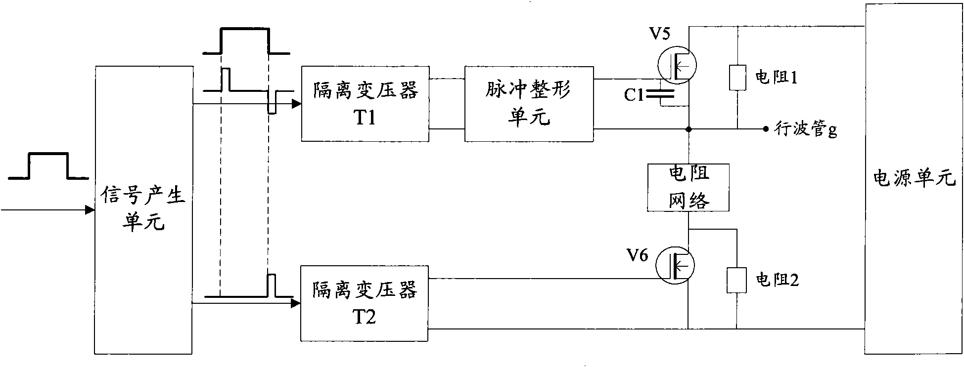
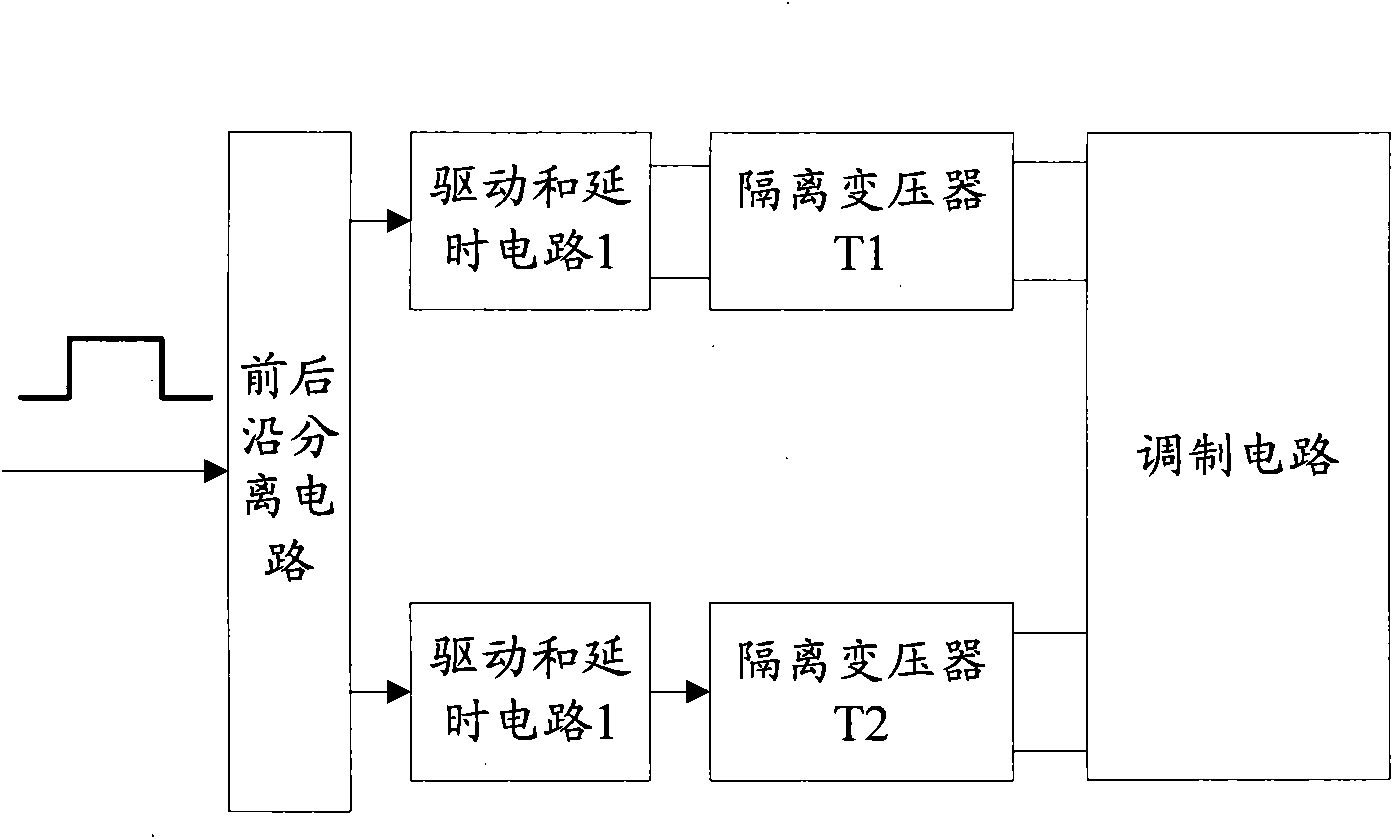
[0041] figure 2 It is a structural block diagram of the floating gate modulator of the present invention. like figure 2 As shown, the floating gate modulator includes: front and rear edge separation circuit, drive and delay circuit 1, drive and delay circuit 2, isolation transformer T1, isolation transformer T2 and modulation circuit; wherein,

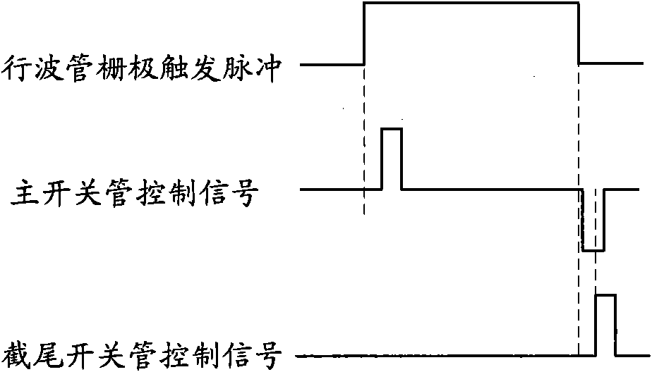
[0042] The front and rear edge separation circuit extracts the front and rear edges of the trigger pulse from the trigger pulse of the TWT gate to form the front negative pulse signal and the rear negative pulse signal; the front negative pulse signal and the rear negative pulse signal are used as the main switching tube The control signal is input to the drive and delay circuit 1, and the trailing edge negative pulse signal is input to the drive and delay circuit 2 as the control signal of the truncated switch...


PUM


Abstract

The invention discloses a floating grid modulator. As a leakage inductance peak adsorption unit is arranged between an isolating transformer and a pulse shaping driver module, the floating grid modulator can adsorb a leakage inductance peak in an output signal of the isolating transformer so as to avoid using a low-leakage inductance transformer with relatively complex preparation process, large volume and high cost; therefore, the cost and volume of the floating grid modulator can be conveniently reduced. An extra capacitor does not need to be connected with the outside of a main switch, and a large-resistance bleeder resistor R9 is combined with an inherent distributed capacitor in the main switch to maintain the conduction level of the main switch, so that the volume of the floating grid modulator is reduced. Signal driving is realized by using a driver IR2110, and the common conduction time of the main switch and a truncated switch tube is reduced by using the time delay characteristic of the device, so the circuit loss is reduced and the efficiency is improved.

Description

technical field [0001] The invention relates to the field of electronic technology, in particular to a floating gate modulator of building block power components used in communication, guidance and electronic countermeasure equipment, and can also be applied to floating gate modulators of other electric vacuum amplifiers. Background technique [0002] The microwave power module is a building block power component mainly used in electronic system equipment such as microwave data link communication, radar, electronic countermeasures and guidance instruments. In the broadband microwave power module, the high-power amplifier uses a miniature traveling wave tube (VPB). The floating gate modulator that controls the operation of the VPB becomes an important part of the microwave power module. The main technical indicators and application requirements of the microwave power module are similar to those of the floating The technical realization of the gate modulator is related to the ...

Claims


Application Information

Patent Timeline
IPC IPC(8): H03K5/01H03K17/04H03K5/06
Inventor 王斌谢章贵黎滨夏志军朱元江
Owner 中国船舶重工集团公司第七二三研究所
Why Eureka
Try Eureka