Circular tomosynthesis x-ray tube

A technology of X-ray tube and X-ray, applied in the field of X-ray tube and X-ray inspection device

Inactive Publication Date: 2011-02-02
KONINKLIJKE PHILIPS ELECTRONICS NV
View PDF1 Cites 7 Cited by
  • Summary
  • Abstract
  • Description
  • Claims
  • Application Information

AI Technical Summary

Problems solved by technology

[0004] However, such devices require multiple detectors, resulting in a high effort on the detector side due to the need for multiple detectors

Method used


Image

  • Circular tomosynthesis x-ray tube
  • Circular tomosynthesis x-ray tube
  • Circular tomosynthesis x-ray tube

Examples


Embodiment Construction

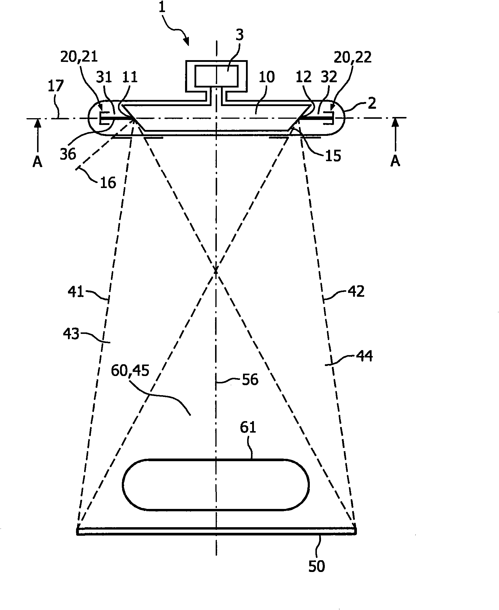
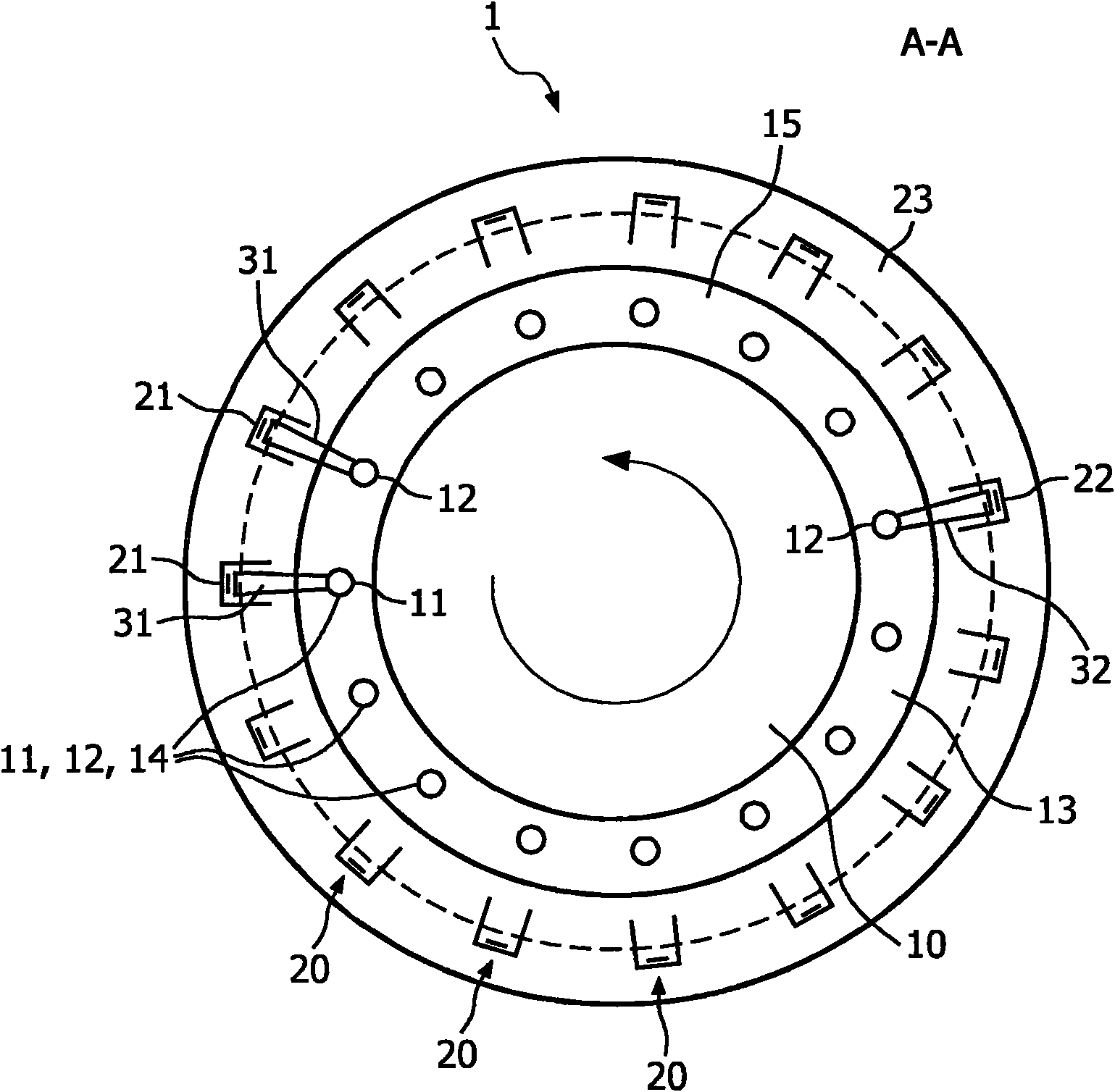
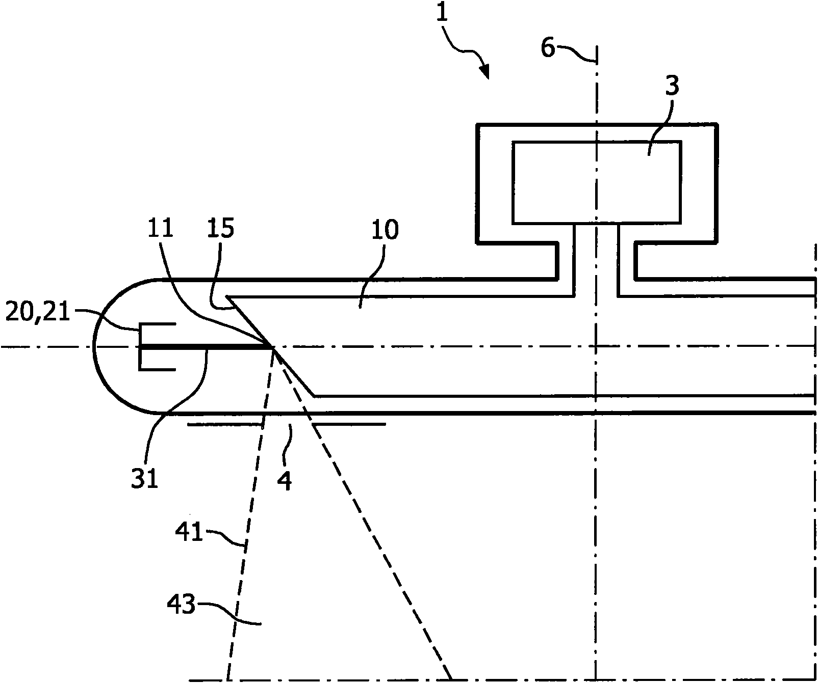
[0054] figure 1 An X-ray tube 1 is shown in the figure. An anode arrangement 10 is provided in the housing 2 of the x-ray tube 1 , which can be rotated by the electric motor 3 in order to avoid damage to the path of the focal spot. The anode arrangement 10 may be provided with a plurality of focal spot positions 11, 12, however, the focal spot positions do not necessarily correspond to fixed positions on the anode surface since the surface of the anode 10 may rotate during operation. The focal spot positions 11, 12 should be considered to be the respective positions where the electron beams 31, 32 encounter the anode arrangement. It should be noted that the anode arrangement 10 can also be provided with a larger number of focal spots or focal spot positions. Inside the housing 2 there is also a cathode arrangement 20 having a plurality of electrodes including a first cathode 21 and a second cathode 22 . It should also be noted that the number of cathodes and focal spot posi...


PUM


Abstract

Tomosynthesis system with a rotating anode X-ray tube enabling a circular scan trajectory, wherein the X-raytube 1 may be equipped witha large number ofcathodes (21, 22) distributed around an anode. This allows to generate X-rays (41, 42) at focal spot positions (11, 12), for example evenly distributed on a for example circular line (14) on the surface (15) of an anode (10). The object (61) may be located on the (10) axis of rotation (6) of the anode at some distance to the source. For an examination, the object (61) may be exposed to X-raybeams (41, 42) generated successively on all focal spot positions (11, 12), wherein no movement of the X-raytube 1 isnecessary. The transmitted X-rayintensities may be measured by a flat panel detector (50) to achieve a reconstructed three-dimensional image data.

Description

technical field [0001] The present invention relates to an X-ray tube and an X-ray examination device and a corresponding method for circular tomosynthesis, in particular to an X-ray tube and an X-ray examination device and a corresponding method capable of providing improved image quality. Background technique [0002] Digital tomosynthesis is currently being discussed as the next breast screening technology because it produces three-dimensional data with doses comparable to conventional mammography. In current tomosynthesis systems for mammography, the x-ray source is moved along a circular arc or line around the object during data acquisition. However, this is disadvantageous for several reasons. Movement of the X-ray source is intractable and takes acquisition time. Furthermore, source trajectories are sub-optimal because source trajectories cause asymmetrical image artifacts produced by the time necessary to move along a circular arc or line. [0003] For example fro...

Claims


Application Information

Patent Timeline
Patent Type & Authority Applications(China)
IPC IPC(8): H01J35/06H01J35/14
CPCH01J35/065H01J2235/066H01J2235/062H01J2235/068H01J35/14H01J35/153
Inventor A·特伦K·埃哈德
Owner KONINKLIJKE PHILIPS ELECTRONICS NV
Why Eureka
Try Eureka