High-efficiency tilted plate sand-removal and water-intake device

A technology of water intake device and sloping plate, which is applied in the field of high-efficiency sloping plate sand removal and water intake device, can solve the problems of low sand removal efficiency, unsatisfactory fine sand removal effect, and difficulty in reaching the predetermined target, so as to achieve improved sand removal efficiency and structural Compactness and the effect of reducing water intake costs

Inactive Publication Date: 2011-02-09
CHONGQING UNIV
View PDF2 Cites 6 Cited by
  • Summary
  • Abstract
  • Description
  • Claims
  • Application Information

AI Technical Summary

Problems solved by technology

However, the prevention and removal of large particles of sediment (such as particle size greater than 0.1mm) or floating objects in these water intake devices is not ideal for the removal of fine sand, and the conventional upflow inclined plate water intake device is not ideal. In use, it is also restricted by water depth
According to relevant reports, in the Yangtze River Basin, due to the construction of cascade hydropower stations in the upper reaches, although the sediment concentration is still high during the flood season, it has shown a trend of fine sand particles, which makes the sand removal efficiency of the water intake device developed at present Very low, so it is often difficult to achieve the intended target in practical applications

Method used


Image

  • High-efficiency tilted plate sand-removal and water-intake device
  • High-efficiency tilted plate sand-removal and water-intake device
  • High-efficiency tilted plate sand-removal and water-intake device

Examples


Embodiment Construction

[0023] The present invention will be further described below in conjunction with the accompanying drawings and specific embodiments.

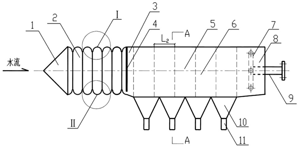
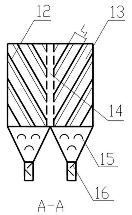
[0024] Such as figure 1 As shown, the high-efficiency inclined plate sand removal and water intake device is composed of three parts: the water inlet chamber 2, the sediment separation and self-cleaning chamber 5 and the water outlet chamber 8. The water inlet chamber 2 is located at the forefront of the water intake device, and its front portion is provided with a conical front cover 1 . The sediment separation and self-cleaning chamber 5 is located in the middle of the water intake device, the water outlet chamber 8 is connected to the rear end of the sediment separation and self-cleaning chamber 5, and the outlet pipe 9 is connected to the end of the water collecting pipe 7 .

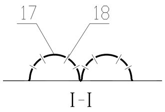
[0025] The water inlet chamber 2 is assembled into a tube with a rectangular cross section by using four corrugated folded plates 17, the direction of the corrugatio...


PUM


Abstract

The invention relates to a high-efficiency tilted plate sand-removal and water-intake device which is used as water intake equipment in water supply engineering and surface water source heat pump engineering. The device comprises a water inlet chamber, a sand-separating and self-cleaning chamber and a water outlet chamber, wherein the wall of the intake chamber is made of corrugated bent plates and is provided with countless water inlet holes and water inlet/sand discharge dual-purpose holes; and the upper half of the sand-separating and self-cleaning chamber is a sand-separating chamber, the lower half is connected with a self-cleaning sand discharge bucket and a sand discharge pipe, a plurality of lateral flow tilted plates are arranged in bilateral symmetry in the direction of water flow in the sand-separating chamber, the tilted plates are tilted downwards and are provided with fins which are perpendicular to the direction of water flow and the plane of the tilted plates, and a sand-settling channel is left in the symmetry axis position of left and right lateral flow tilted plates and is communicated with the self-cleaning sand discharge bucket at the lower part. The device can be widely used in rivers having a high floater and sand content, and can be also used in water intake engineering using lakes, reservoirs or other water bodies as the water source. Besides, the device can effectively prevent the blocking of weeds and other floaters in water, effectively remove sand in water, omit the special sand basin and simplify the subsequent water treatment process, thereby achieving the purposes of reducing the abrasion of water pump impellers and subsequent water treatment structures, saving the capital investment, saving the occupied area and lowering the water intaking cost.

Description

technical field [0001] The invention belongs to a water intake device, in particular to a high-efficiency inclined plate sand removal water intake device for effective weed control and efficient sand removal. Background technique [0002] Using rivers, lakes, etc. as water sources is an important form of water resources development and utilization in many areas of our country, especially in the southern area, affected by ground erosion during rainfall, the river has a high sediment content, and there are many floating objects such as aquatic plants in the water body, often or It will block the water intake unit, or it will adversely affect the subsequent water pumps and water treatment equipment. Therefore, obtaining good surface water sources as much as possible is a necessary measure for urban water supply projects and surface water source heat pump projects. [0003] For a long time, in order to obtain water quality with low sand content and avoid the influence of floati...

Claims


Application Information

Patent Timeline
Patent Type & Authority Applications(China)
IPC IPC(8): B01D21/24E03B3/04B01D21/02
Inventor 姜文超倪建华张智龙天渝胥标尹浩赵玉静
Owner CHONGQING UNIV
Why Eureka
Try Eureka