Ion-conducting membrane structure

A technology of ion-conducting membranes and membrane electrode assemblies, which can be applied to structural parts, fuel cells, coatings, etc., and can solve problems such as low MEA performance and reduced efficiency

Inactive Publication Date: 2011-02-09
JOHNSON MATTHEY FUEL CELLS LTD
View PDF7 Cites 16 Cited by
  • Summary
  • Abstract
  • Description
  • Claims
  • Application Information

AI Technical Summary

Problems solved by technology

The much thinner ion-conducting membranes currently employed face significantly greater durability challenges...

Method used


Image

  • Ion-conducting membrane structure
  • Ion-conducting membrane structure
  • Ion-conducting membrane structure

Examples


Embodiment Construction

[0059] best practice

[0060] The structure of the ion-conducting membrane of the present invention will be described in more detail below with reference to the drawings and examples.

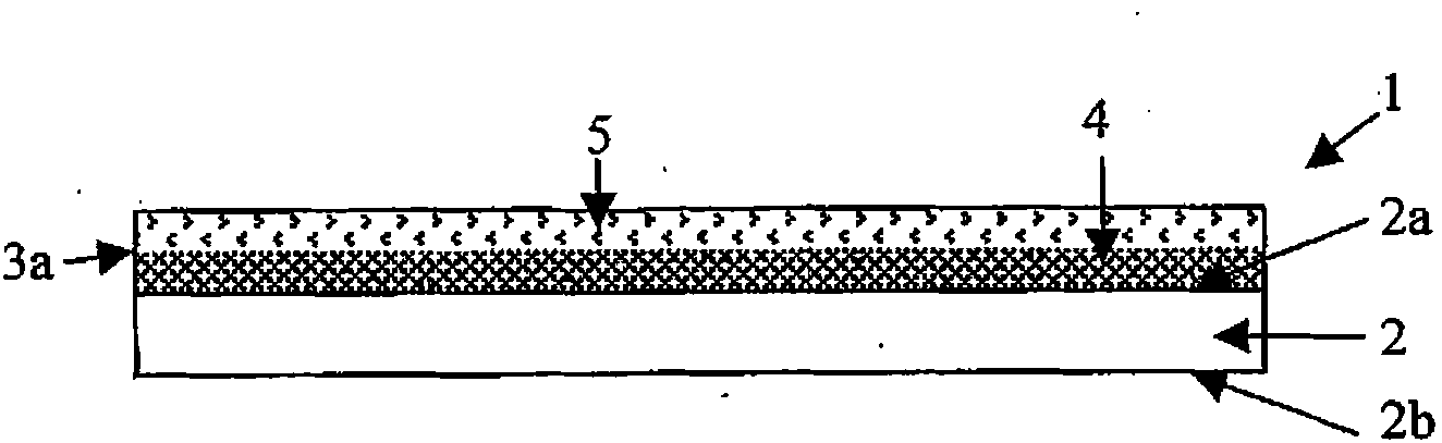
[0061] figure 1 A schematic cross-sectional view showing an ion-conducting membrane structure of the present invention, said structure comprising an ion-conducting membrane, a first hydrogen peroxide decomposition catalyst and a first free radical scavenger in a separate layer on the first surface of the ion-conducting membrane In the first layer on the face, a first hydrogen peroxide decomposition catalyst is adjacent to the ion conducting membrane.

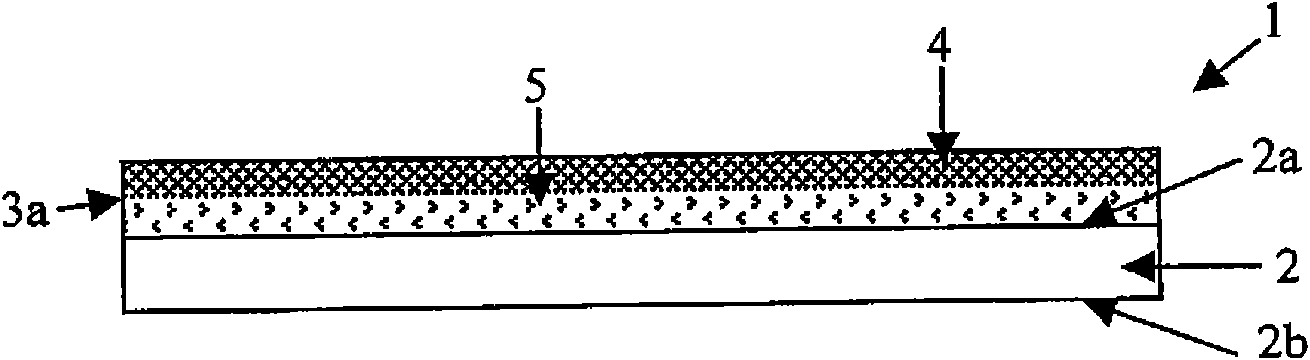
[0062] figure 2 A schematic cross-sectional view showing an ion-conducting membrane structure of the present invention, said structure comprising an ion-conducting membrane, a first hydrogen peroxide decomposition catalyst and a first free radical scavenger in a separate layer on the first surface of the ion-conducting membrane In the first l...


PUM


Abstract

An ion-conducting membrane structure comprising (i) an ion-conducting membrane wherein said membrane has a first face and a second face, (ii) a first hydrogen peroxide decomposition catalyst and (iii) a first radical scavenger, wherein the first hydrogen peroxide decomposition catalyst is in a first layer on the first face of the ion-conducting membrane in an amount from 0.01 to 15[mu]g/cm2 or the first hydrogen peroxide decomposition catalyst in embedded within the ion-conducting membrane in an amount from 0.001 to 5% by weight is disclosed.

Description

field of invention [0001] The present invention relates to a novel ion-conducting membrane structure suitable for use in electrochemical devices such as fuel cells. Background technique [0002] A fuel cell is an electrochemical cell comprising two electrodes separated by an electrolyte. A fuel such as hydrogen or an alcohol such as methanol or ethanol is supplied to the anode, and an oxidant such as oxygen or air is supplied to the cathode. Electrochemical reactions take place at the electrodes, converting the chemical energy of the fuel and oxidant into electricity and heat. Electrocatalysts are used to facilitate the electrochemical oxidation of fuel at the anode and the electrochemical reduction of oxygen at the cathode. [0003] In proton exchange membrane (PEM) fuel cells, the electrolyte is a solid polymer membrane. The membrane is electronically insulating but ionically conducting. The membrane is generally proton conducting, and protons produced at the anode are...

Claims


Application Information

Patent Timeline
IPC IPC(8): H01M8/10
CPCH01M2300/0094Y02E60/521H01M2300/0082H01M8/1053H01M8/1051Y02E60/50C08J7/04H01M8/02H01M8/1004
Inventor D·E·巴恩韦尔A·J·霍奇金森T·R·拉尔夫
Owner JOHNSON MATTHEY FUEL CELLS LTD
Why Eureka
Try Eureka