Apparatus for performing beam tracking process and method thereof

A technology of beam tracking and beam pattern, applied to the device for performing beam tracking processing and its field, can solve the problems of increasing time and achieve the effect of reducing the number

Inactive Publication Date: 2011-02-09
LG ELECTRONICS INC
View PDF4 Cites 13 Cited by
  • Summary
  • Abstract
  • Description
  • Claims
  • Application Information

AI Technical Summary

Problems solved by technology

However, if the number of beam links in a given network increases, the time required to perform beam search and tracking increases

Method used


Image

  • Apparatus for performing beam tracking process and method thereof
  • Apparatus for performing beam tracking process and method thereof
  • Apparatus for performing beam tracking process and method thereof

Examples


Embodiment Construction

[0078] Preferred embodiments of the present invention will now be described with reference to the accompanying drawings. However, the embodiments of the present invention described below can be modified into various other forms, and the scope of the present invention is not limited to the embodiments.

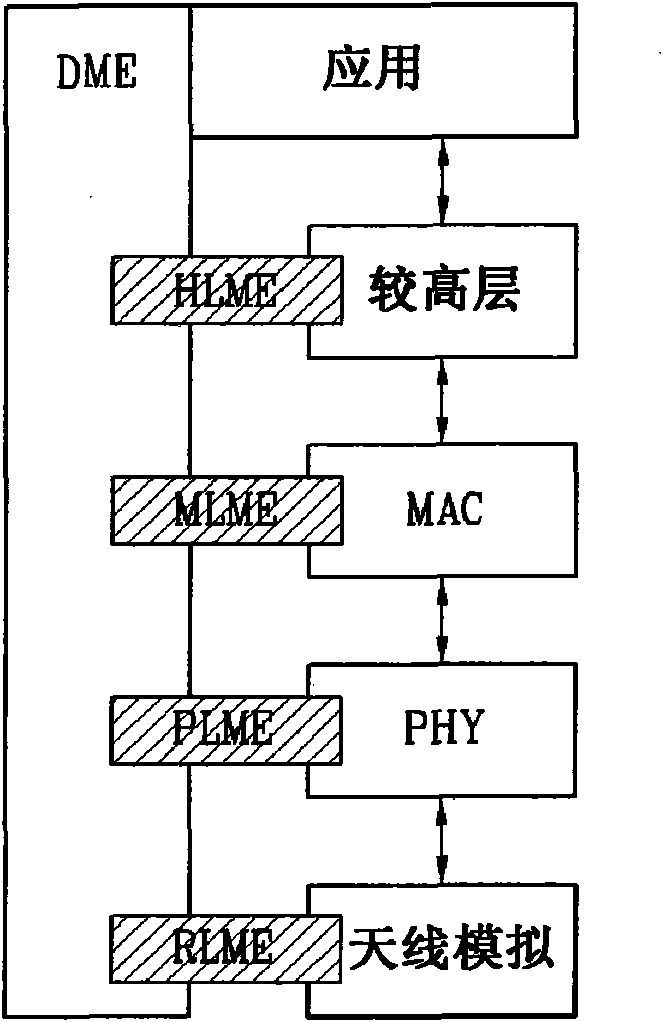
[0079] figure 1 A layered structure according to the invention is illustrated.

[0080] The layered structure includes application layer, higher layer, MAC layer and PHY layer. The application layer is connected to the device management element (DME), the higher layers are connected to the DME through the higher layer management element (HLME), the MAC layer is connected to the DME through the MAC layer management element (MLME), and the PHY layer is connected to the PHY layer management element (PLME) Connect to DME.

[0081] In the case of highly directional wireless communication such as mmWave, it is also necessary to consider the RF / analog front-end as a layer to achiev...


PUM


Abstract

A method for performing beam tracking in a wireless communication network is provided. In the method, a transmitter station emits beam patterns including respective beam pattern indices to receiver stations and receives a feedback index indicating one of the beam patterns from each receiver station during a predetermined channel time after the emission of beam patterns is completed. A beam pattern feedback is processed using a simple code, thereby minimizing the amount of information and hardware required for beam search and tracking. In addition, in uni-directional beam tracking, it is possible to perform tracking on a number of beam links at once and a sub-channel that can be used for beam tracking and search is allocated to each station to allow a number of stations to simultaneously perform beam search, thereby reducing the amount of used channel time.

Description

technical field [0001] The present invention relates to a method and apparatus for allocating beam search time required for highly directional radio transmissions to perform efficient beam search and tracking. Background technique [0002] In a multiple-input multiple-output (MIMO) communication system, a transmitter station uses multiple transmit antennas and a receiver station uses multiple receive antennas for data communications. A single MIMO channel created by an antenna can be broken down into independent channels. Each independent channel is a sub-channel (or transport channel) in the spatial domain of the MIMO channel and occupies a range. MIMO systems may exhibit improved performance (eg, improved transmit capability) when using the additional range created by the multiple antennas. [0003] MIMO systems are classified into two types, open loop and closed loop. In an open-loop system, space-time coding techniques are typically implemented in the MIMO transmitter...

Claims


Application Information

Patent Timeline
Patent Type & Authority Applications(China)
IPC IPC(8): H04W16/28H04W72/08H04B7/06
CPCH04B7/0632H04B7/043H04B7/0619H04L27/2613H04B7/0617H04B7/0695
Inventor 全范镇
Owner LG ELECTRONICS INC
Why Eureka
Try Eureka