
Pressure sensor reading method

A pressure sensor and reading technology, used in vascular assessment, cardiac catheterization, etc., can solve the problems of phase difference, slow pressure reading change, reading lag, etc.

Inactive Publication Date: 2011-02-16
ZHEJIANG GONGSHANG UNIVERSITY
View PDF3 Cites 7 Cited by
  • Summary
  • Abstract
  • Description
  • Claims
  • Application Information

AI Technical Summary

Problems solved by technology

But the side effect is the loss of dynamic characteristics, that is, the pressure reading changes slowly. During the rapid inflation and slow deflation process of the sphygmomanometer, the reading often lags behind the actual pressure change value greatly, and there is a certain phase difference.

Method used


Image

  • Pressure sensor reading method
  • Pressure sensor reading method
  • Pressure sensor reading method

Examples


Embodiment Construction

[0039] In conjunction with accompanying drawing, the present invention is described in detail as follows:

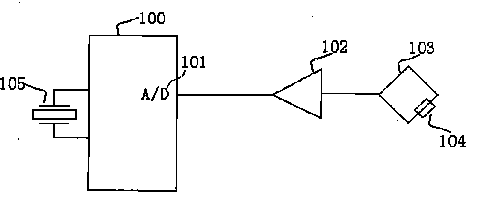
[0040] like figure 1 Shown, pressure transducer-single-chip microcomputer A / D coupling sampling system comprises: single-chip microcomputer (100), preferred PIC16F84, this chip carries the A / D port (101) that can be expanded to 10 bits, and crystal oscillator (105) has determined its work The speed and the highest sampling frequency are preferably 4MHz. The pressure sensor (104) forms an electric bridge (103), and after the signal conditioning of the operational amplifier (102), it is sent to the A / D port (101) for sampling.

[0041] In the entire coupling system, there are not only errors of the pressure sensor (104), but also errors of the A / D port (101), as well as errors such as electromagnetic interference, power supply fluctuations, and reference potential fluctuations. These errors will cause the final display to jitter.

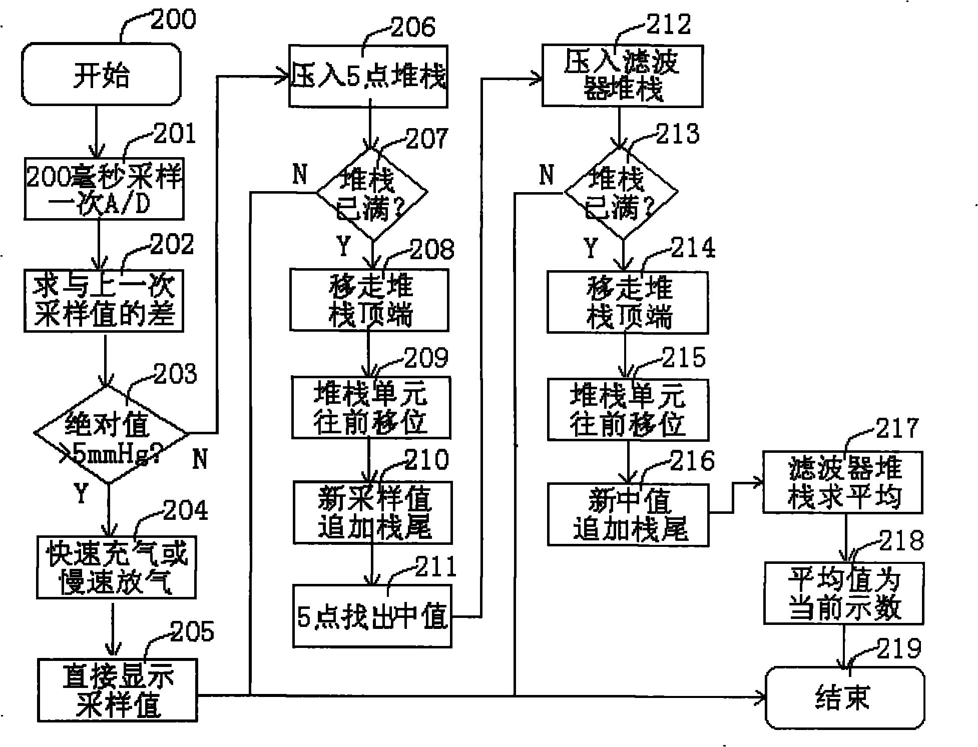
[0042] like figure 2 Shown, concrete s...


PUM


Abstract

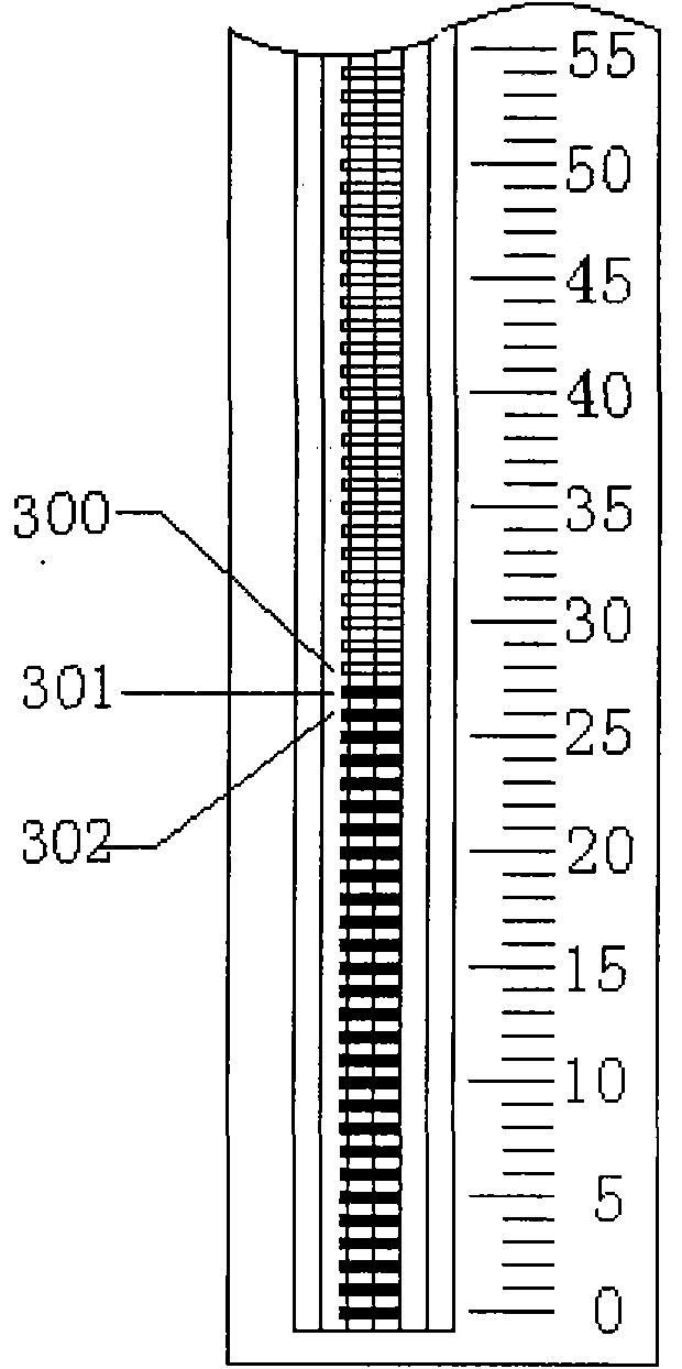
The invention discloses a pressure sensor reading method, which is a digital pressure sensor display method for a column display electronic sphygmomanometer. The rapid inflation, slow deflation and static measuring states of the sphygmomanometer are detected, low-pass filtering is performed on the static measuring state and dynamic states of rapid inflation and slow deflation are not processed, so that measuring accuracy can be ensured, reading shake is eliminated, dynamic following performance can be enhanced and Korotkoff sound reading is not affected. Components are arranged in a compact singlechip system. The method has the advantages of high measuring accuracy, stable reading, high readability, low cost and the like.

Description

technical field [0001] The invention relates to a pressure sensor display method, in particular to a pressure sensor digital display method applied to a column display electronic sphygmomanometer, which takes into account the static and dynamic characteristics of the pressure sensor, and belongs to the technical field of sphygmomanometer and blood pressure measurement. Background technique [0002] Sphygmomanometer is a kind of pressure gauge. At present, blood pressure measurement mainly includes mechanical sphygmomanometer, mercury tonometer, oscillometric electronic sphygmomanometer, optical fiber sphygmomanometer, column display sphygmomanometer and other measuring instruments. The oscillometric electronic sphygmomanometer is mainly used in the family and health care markets. Due to its low measurement accuracy and poor repeatability, as a medical measuring instrument with medical diagnostic indications, it cannot be accepted by the majority of medical institutions; the t...

Claims


Application Information

Patent Timeline
IPC IPC(8): A61B5/023
Inventor 赵文敏朱安定邢建国
Owner ZHEJIANG GONGSHANG UNIVERSITY
Learn More