Automatic aligning assembly system for micro members

An automatic alignment and assembly system technology, applied in metal processing, metal processing equipment, manufacturing tools, etc., can solve the problems of difficulty in establishing standard templates, low precision, low assembly efficiency, etc., to avoid adhesion effects, high-precision swing The effect of positioning

Active Publication Date: 2011-02-16
BEIJING INSTITUTE OF TECHNOLOGYGY
View PDF9 Cites 26 Cited by
  • Summary
  • Abstract
  • Description
  • Claims
  • Application Information

AI Technical Summary

Problems solved by technology

This assembly method results in a large time-consuming, low assembly efficiency, and poor consistency of assembly accuracy
In addition, for accurate alignment, the respective orientations of the two images must first be dete

Method used


Image

  • Automatic aligning assembly system for micro members
  • Automatic aligning assembly system for micro members
  • Automatic aligning assembly system for micro members

Examples


Embodiment Construction

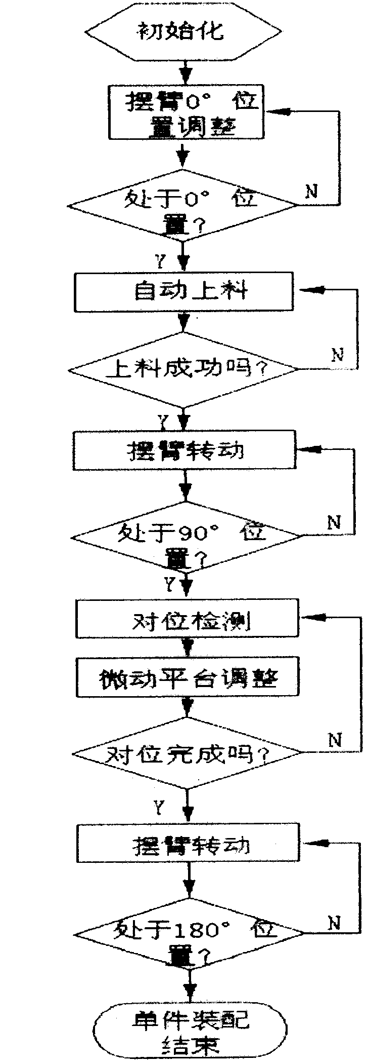
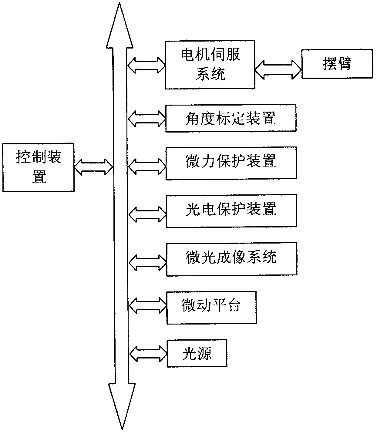
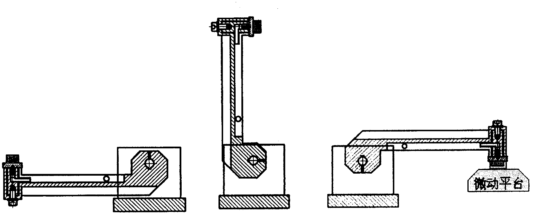
[0035] The invention is an automatic alignment assembly system for micro-sized structural parts, including a control device, an angle calibration device, a motor servo system, a swing arm, a three-dimensional beam splitter, a microscopic camera device, a micro-force sensing protection device, a light source and a photoelectric Sensing protection device; wherein, the microscopic camera device is located directly above the stereoscopic beam splitter, the micro-motion platform is located directly below the stereoscopic beam splitter, the swing arm is connected to the motor servo system, and the micro force sensing protection device and the photoelectric sensing protection device are respectively connected to the swing arm;

[0036] A control device, including a rotation control module, an angle test module, an image processing module, a micro-motion platform control module, an external control module, and a light source control module;

[0037] The rotation control module is used...


PUM


Abstract

The invention discloses an automatic aligning assembly system for micro members and belongs to the field of automatic control. The system has a function of assembling a part to be assembled on a basic part accurately and preventing the part to be assembled and the basic part from squeezing each other and being damaged. In the system, a control device is adopted, a motor servo system is adopted to control the rotation of a swing arm, an angle calibration device makes the rotation angle of the swing arm more accurate by testing the rotation angle, and a micro displacement worktable is adjusted to be able to rotate in six degrees of freedom by performing the corresponding calculation of images acquired by a microscope imaging system, so that the basic part and the part to be assembled can be matched accurately. In the invention, by regulating the operation of all parts through the control device, the assembly efficiency and precision are improved.

Description

technical field [0001] The invention relates to an automatic alignment assembly system for micro-sized structural parts, which belongs to the field of automatic control. Background technique [0002] Existing assembly systems for micro-sized structural parts generally have a vision system, most of which only play a monitoring role. The motion operation is realized by a combination of multiple manipulators and multiple degrees of freedom, and the random error is relatively large during the operation process. The operator controls the movement of the robot through the relative position of the assembly on the monitor to realize the tentative assembly operation. This assembly method results in large time consumption, low assembly efficiency, and poor consistency of assembly accuracy. In addition, for accurate alignment, the respective orientations of the two images must first be determined. The traditional method for determining orientations is through image template matching, ...

Claims


Application Information

Patent Timeline
IPC IPC(8): B23P19/00
Inventor 张之敬王强叶鑫金鑫
Owner BEIJING INSTITUTE OF TECHNOLOGYGY
Why Eureka
Try Eureka