

Mechanical clamping device for rotary workbench
A technology of rotary table and clamping device, which is applied in the direction of metal processing machinery parts, manufacturing tools, metal processing equipment, etc., and can solve the problems of heavy load of rotary table, large and small clamping force of clamping device, etc. , to achieve the effect of simple structure, reliable clamping and large clamping force
- Summary
- Abstract
- Description
- Claims
- Application Information
AI Technical Summary
Problems solved by technology
Method used
Image

Examples
Embodiment Construction
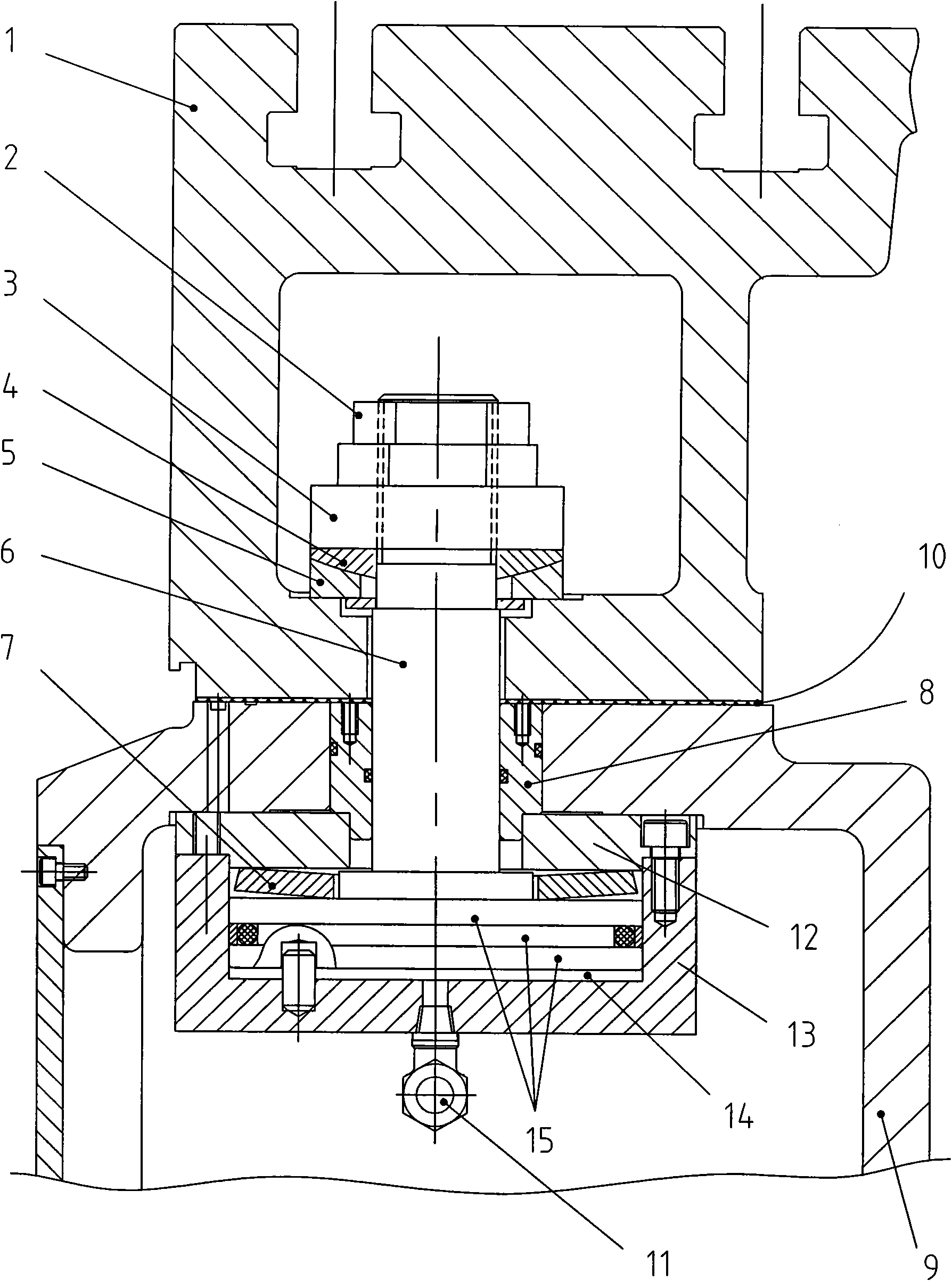
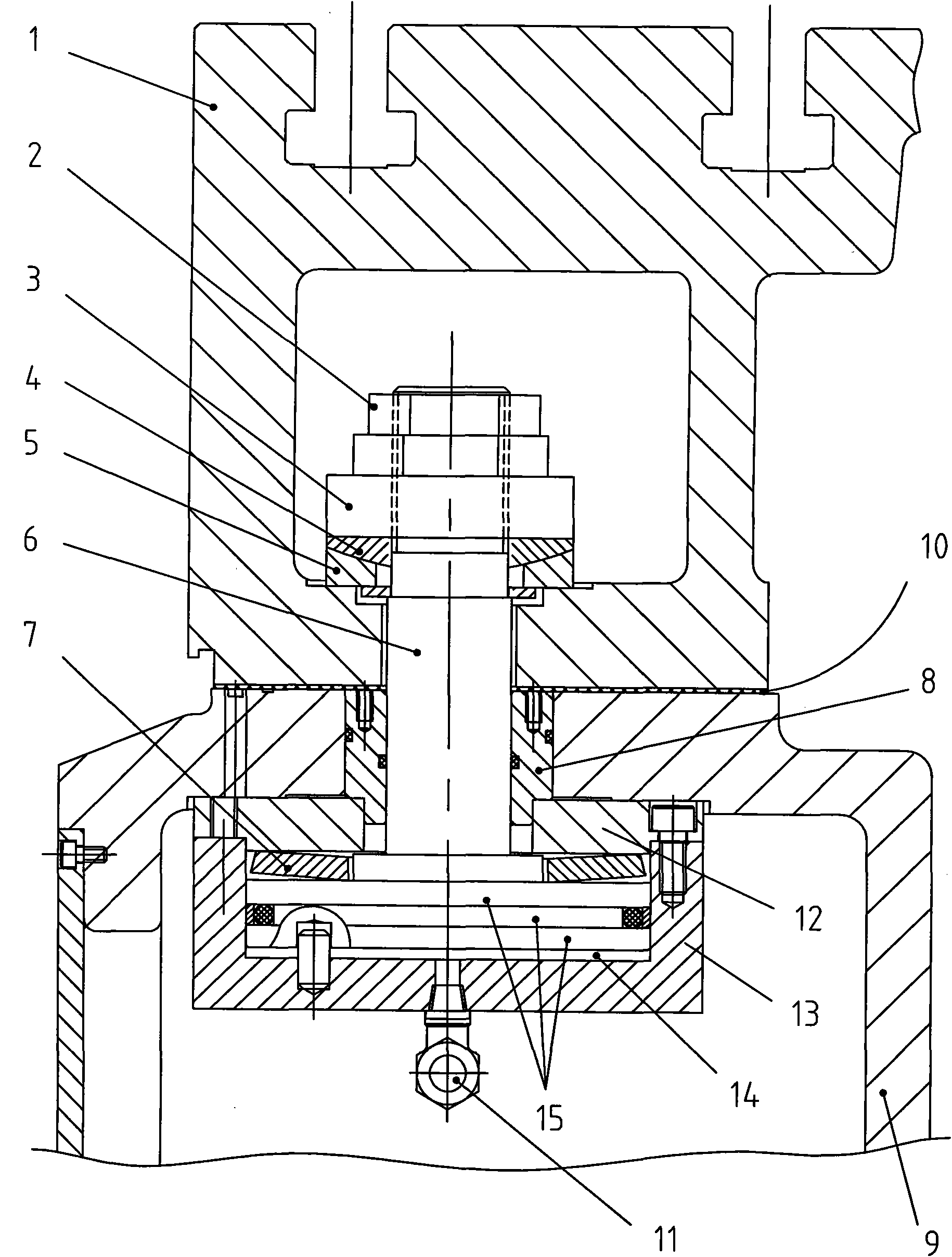
[0011] Such as figure 1 As shown: 1 is the rotary workbench at the top, 9 is the slide body located at the bottom, and there is a sliding guide rail surface 10 between the slide body 9 and the workbench 1 .
[0012] A piston shaft 6 penetrates between the slide body 9 and the workbench 1, the piston shaft 6 is connected to the piston 15 below, and the piston 15 is equipped with an oil cylinder 13, and the upper bolt of the oil cylinder 13 is fixed with an oil cylinder upper cover 12, and the bottom surface of the piston 15 is A lower cavity 14 is formed with the bottom of the oil cylinder 13, and a seal ring groove is arranged on the outer circumference of the piston 15 and a seal ring is housed. A hydraulic oil port 11 is threadedly connected to the bottom end surface of the oil cylinder 13 .
[0013] The upper end of the piston shaft 6 is threaded with a clamping nut, and the clamping nut is composed of a preload adjustment nut 3 threaded with the piston shaft 6 and a lock ...
PUM
 Abstract
Description
Claims
Application Information