
Automatic material replacing and connecting device and prepressing gas circuit

A feeding device and automatic technology, applied in the direction of cardboard articles, etc., can solve the problems of complex operation process, unsatisfactory cylinder pressure, increase production cost, etc., and achieve the effect of reducing manufacturing cost, reducing production cost and simple operation.

Active Publication Date: 2013-09-25
杭州珂瑞特新机械制造有限公司
View PDF1 Cites 0 Cited by
  • Summary
  • Abstract
  • Description
  • Claims
  • Application Information

AI Technical Summary

Problems solved by technology

Its disadvantages: 1. The cutting mechanism and the material receiving mechanism are independent of each other and need to be controlled by cylinders separately, which increases the production cost and complicates the operation process; 2. The air pressure of the cylinder is not controlled by the pre-compression air circuit, so the pressure of the cylinder cannot be controlled. meet different needs

Method used


Image

  • Automatic material replacing and connecting device and prepressing gas circuit
  • Automatic material replacing and connecting device and prepressing gas circuit
  • Automatic material replacing and connecting device and prepressing gas circuit

Examples


Embodiment 1

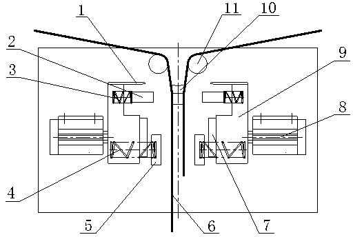
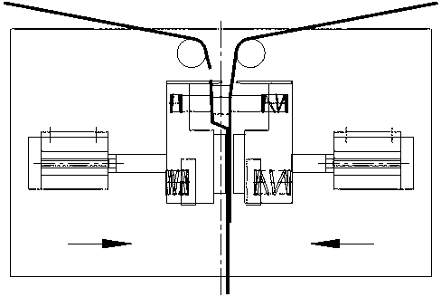
[0010] Embodiment 1: with reference to attached Figure 1-5 . The automatic material changing device and the pre-compressed air circuit include a cylinder 8, the piston rod of the cylinder 8 is connected with a slider 9, and the two sliders 9 are symmetrical to each other, and the slider 9 is equipped with a cutting mechanism and a material receiving mechanism. Above the material receiving mechanism, two material sticks 11 are arranged above the slide block 9 . The cutting mechanism is composed of a cutter 1, a buffer device and a bottom knife 10. The cutter 1 is installed above the slider 9 and is left-right symmetrical. The buffer device is composed of a small buffer plate 2 and a buffer spring 3. On the block 9, the other end connects the small buffer sheet 2, and the working surface of the small buffer sheet 2 matches with the working surface of the bottom knife 10, and the bottom knife 10 is fixedly installed on the overall production equipment. The material receiving m...

Embodiment 2

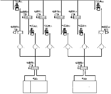
[0011] Embodiment 2: On the basis of Embodiment 1, when the left side extends into the stock, the solenoid valve B 1 and D 1 Pilot air path, barometer B 1 Boost the pressure to 1.5 bar, so that the cylinder A punches 1.5 bar. At this time, the small buffer plate 2 on the left presses the stock, but the left cutter 1 is not in contact with the bottom knife 10; the solenoid valve A 2 and D 2 The air circuit is connected, and the cylinder B presses 6 bar. At this time, the small buffer sheet 2 on the right presses the material, and the cutter 1 cuts the material. At this time, the left and right large buffer sheets 7 also have a certain pressing force on each other; the solenoid valve C 1 Action, Barometer C 1 Boost the pressure to 4 bar, so that the cylinder A is pressurized to 4 bar. At this time, the pressing force between the left and right large buffer plates 7 increases, thereby crimping the two materials; finally, the solenoid valve D 1 and D 2 action, cylinder A an...


PUM


Abstract

The invention relates to an automatic material replacing and connecting device and a prepressing gas circuit. In the automatic material replacing and connecting device, different requirements on a cylinder pressure in different production processes are met by utilizing the prepressing gas circuit; and moreover, a cutting mechanism and a material connecting mechanism are controlled by the same cylinder. The automatic material replacing and connecting device comprises the cylinder, wherein the piston rod of the cylinder is connected with slide blocks; the two slide blocks are in bilateral symmetry; the slide blocks are provided with the cutting mechanism and the material connecting device; the cutting mechanism consists of cutters, buffering devices and a dead knife; the cutters are arranged above the slide blocks and are in bilateral symmetry; and the dead knife is fixedly arranged on overall production equipment. The material connecting mechanism consists of big buffer plates and boosting devices; the big buffer plates are fixedly arranged on the slide blocks and are in bilateral symmetry; and the cylinder is controlled by a prepressing gas circuit control system. The automatic material replacing and material connecting device has the advantages that: first, the manufacturing cost is low; second, the device has a simple structure and is convenient to operate; third, material cutting and material connecting operations are stable, reliable and effective; fourth, the device is convenient to maintain and protect; and fifth, the application range is wide.

Description

technical field [0001] The invention relates to an automatic material changing device and a pre-compression air circuit controlled by an electromagnetic valve and capable of automatically cutting off and switching sanitary product materials, and belongs to the technical field of sanitary product production equipment. Background technique [0002] CN200963916, the name is "automatic disconnection and connection device for raw materials of sanitary products". It includes a frame, the bottom knife is located on the frame, the two cylinder cutting devices are respectively located on both sides of the bottom knife and opposite to the surface of the bed knife, the cylinder feeding device is located on the frame below the cylinder cutting device, the surface of the base The faces of the feeding heads of the cylinder material receiving device are opposite, and the rack feeding rollers located below the cylinder material cutting device are respectively located above the cylinder mate...

Claims


Application Information

Patent Timeline
Patent Type & Authority Patents(China)
IPC IPC(8): B31D1/04
Inventor 莫正虎李世锦陈世尧徐源泉
Owner 杭州珂瑞特新机械制造有限公司
Learn More