Double-channel turbine bypass bleeding device

A bleed device and double-channel technology, which is applied to gas turbine devices, machines/engines, internal combustion piston engines, etc., can solve the problem of increased mechanical wear of actuators and transmission mechanisms, instability of turbine inlet pressure and waste gas bypass, and impact on turbines. Supercharger engine working stability and other issues to achieve the effect of improving working stability, avoiding constant changes in valve opening, and avoiding abnormal wear and tear

Active Publication Date: 2011-02-16
康跃科技(山东)有限公司
5 Cites 13 Cited by

AI-Extracted Technical Summary

Problems solved by technology

The swing of the valve cover leads to unstable turbine inlet pressure and waste gas bypass flow, which affects the working stability of the turbocharger and even the engine;
[0008] 3...

Abstract

The invention discloses a double-channel turbine bypass bleeding device which comprises a turbine volute, wherein the turbine volute is provided with two inlet channels, the two inlet channels are respectively communicated with a bleeding channel, the outlets of the two bleeding channels are provided with concave valve bases, the concave valve bases are provided with a shared valve cover, and the valve cover and the concave valve base form a slip connection, so that the characteristic curve of the flow of valves and the flow area of the valves almost changes linearly. By using rack-and-pinion transmission, the accurate control on the opening and the flow area of the valves can be realized. Thus, the invention can accurately control the amount of bypass waste gas, thereby realizing the optimum matching of a pressure booster and an engine.

Application Domain

Technology Topic

Forced inductionEngineering +4

Image

  • Double-channel turbine bypass bleeding device
  • Double-channel turbine bypass bleeding device
  • Double-channel turbine bypass bleeding device

Examples

  • Experimental program(1)

Example Embodiment

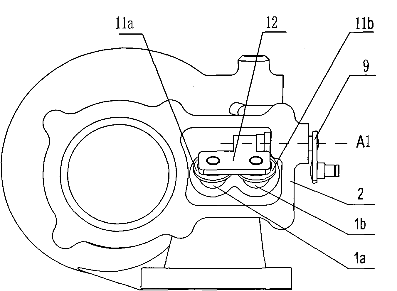
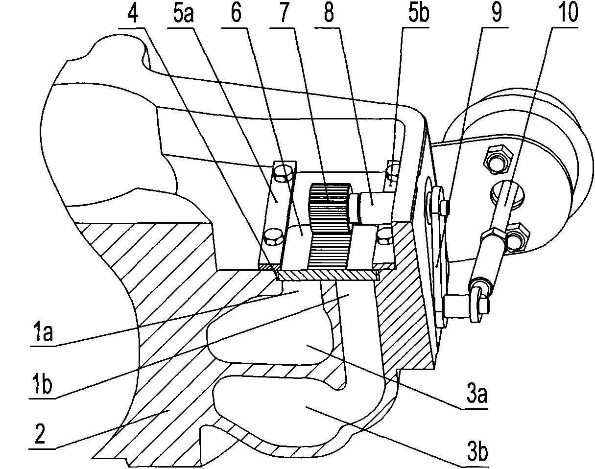
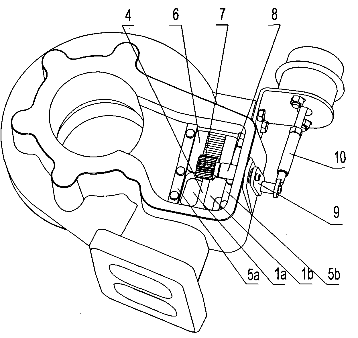
[0032] Examples, as attached figure 2 As shown, a dual-channel turbine bypass bleeder device capable of accurately controlling the valve opening and bypass air discharge volume of a dual-channel turbocharger includes a turbine volute 2 on which is provided The volute first intake passage 3a, the volute second intake passage 3b, the volute first intake passage 3a is connected with a first bleed passage 1a, and the volute second intake passage 3b is connected with a second bleeder An air passage 1b. A concave valve seat 4 is provided at the outlets of the first air release channel 1a and the second air release channel 1b, and a common valve cover 6 is provided on the concave valve seat 4, the valve cover 6 It is in sliding connection with the concave valve seat 4, and the valve cover 6 is in transmission connection with the power driving device.
[0033] The concave valve seat 4 and the valve cover 6 are both rectangular, and both sides of the concave valve seat 4 are provided with a left valve cover pressure plate 5a and a right valve cover pressure plate 5b which are fastened to the turbine volute 3 , The left valve cover pressure plate 5a, the right valve cover pressure plate 5b and the concave valve seat 4 respectively form guide grooves, both sides of the valve cover 6 are located in the guide grooves for the valve cover 6 to slide back and forth to open And close the first bleed passage 1a and the second bleed passage 1b.
[0034] The cross-sections of the first deflation channel 1a and the second deflation channel 1b are rectangular, and are symmetrically distributed in parallel. A valve cover 6 is used to simultaneously control the discharge of the first deflation channel 1a and the second deflation channel 1b. Air volume.
[0035] The power driving device includes an actuator 10 mounted on the turbine volute 2, and the actuator 10 is connected to a transmission mechanism 9 for transmission. The transmission mechanism 9 includes a transmission gear shaft 8 on which a transmission gear is installed. 7. A transmission rack 13 meshed with the transmission gear 7 is installed at the upper middle position of the valve cover 6.
[0036] The valve cover 6 slides under the drive of the transmission gear 7. The transmission gear 7 is driven by the transmission mechanism 9 and the actuator 10 to rotate around the axis A1, pushing the valve cover 6 into the guide groove between the concave valve seat 4 and the left valve cover pressure plate 5a and the right valve cover pressure plate 5b Move inside, thereby opening and closing the first deflation passage 1a and the second deflation passage 1b.
[0037] When the engine is at low speed, the sliding bypass bleeder is in a closed state, and all exhaust gas from the engine enters the turbine to perform work. At medium and high engine speeds, the sliding bypass bleeder is in an open state.
[0038] As attached image 3 As shown, driven by the actuator 10 and the transmission mechanism 9, the transmission gear 7 and the transmission gear shaft 8 rotate, pushing the valve cover 6 between the concave valve seat 4 and the left valve cover pressure plate 5a and the right valve cover pressure plate 5b Slide in the guide groove. Since the flow rate of the sliding valve is basically linear with the valve opening, and the pressure on the valve cover of the sliding valve does not affect the opening of the valve, the actuator can accurately determine the opening of the valve according to the working conditions of the engine. To achieve precise control of bypass air discharge and boost pressure. At this time, the bypass air volume is only related to the exhaust pressure of the engine and the opening of the valve, which completely eliminates the influence of pressure fluctuations caused by the unsteady flow on both sides of the valve cover, and eliminates the impact of the valve cover after the rotary valve is opened. The impact of the pressure fluctuation at the turbine inlet caused by the swing improves the stability of the turbine and the service life of moving parts such as the actuator and the transmission mechanism.
[0039] Now that we have described the invention in detail in accordance with the national patent law, those skilled in the art will recognize the improvement or replacement of the specific embodiments disclosed herein. These modifications are within the spirit and scope of the present invention.

PUM

no PUM

Description & Claims & Application Information

We can also present the details of the Description, Claims and Application information to help users get a comprehensive understanding of the technical details of the patent, such as background art, summary of invention, brief description of drawings, description of embodiments, and other original content. On the other hand, users can also determine the specific scope of protection of the technology through the list of claims; as well as understand the changes in the life cycle of the technology with the presentation of the patent timeline. Login to view more.

Similar technology patents

Classification and recommendation of technical efficacy words

Why Eureka
Try Eureka