Valveless piezoelectric pump of elliptical combined pipe

A technology of valveless piezoelectric pumps and combined tubes, which is applied in the direction of pumps, pump components, variable-capacity pump components, etc., and can solve the problems of large-scale confluence tubes and shunt tubes, unfavorable micro-integration, and small positive and negative flow resistance ratios. and other problems, to achieve the effect of easy flow control, remarkable energy saving effect, and small flow eddy current

Inactive Publication Date: 2011-02-16
JIANGSU UNIV
View PDF7 Cites 13 Cited by
  • Summary
  • Abstract
  • Description
  • Claims
  • Application Information

AI Technical Summary

Problems solved by technology

Commonly used diffusion / shrink tube type valveless piezoelectric pumps have "Y" tube valveless piezoelectric pumps and "V" tube valveless piezoelectric pumps, and the inlet and outlet flow tubes of "Y" tube valveless piezoelectric pumps A "Y" shape is formed by combining a confluence pipe and two diversion pipes. Both the confluence pipe and the diversion pipe are rectangular pipes with equal cross-sections. Integrated
The inlet and outlet flow tubes of the "V" tube valveless piezoelectric pump are composed of a rectangular tube of equal cross-section as a confluence tube and two diffuse (shrink) shunt tubes. On the surface, it leads to difficulties in processing and production. Moreover, the rectangular inlet and outlet flow tubes of equal cross-section make the forward and reverse flow resistance ratio relatively small, which cannot improve the flow rate.

Method used


Image

  • Valveless piezoelectric pump of elliptical combined pipe
  • Valveless piezoelectric pump of elliptical combined pipe
  • Valveless piezoelectric pump of elliptical combined pipe

Examples


Embodiment Construction

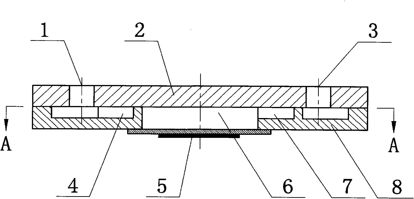
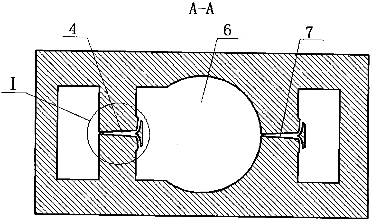
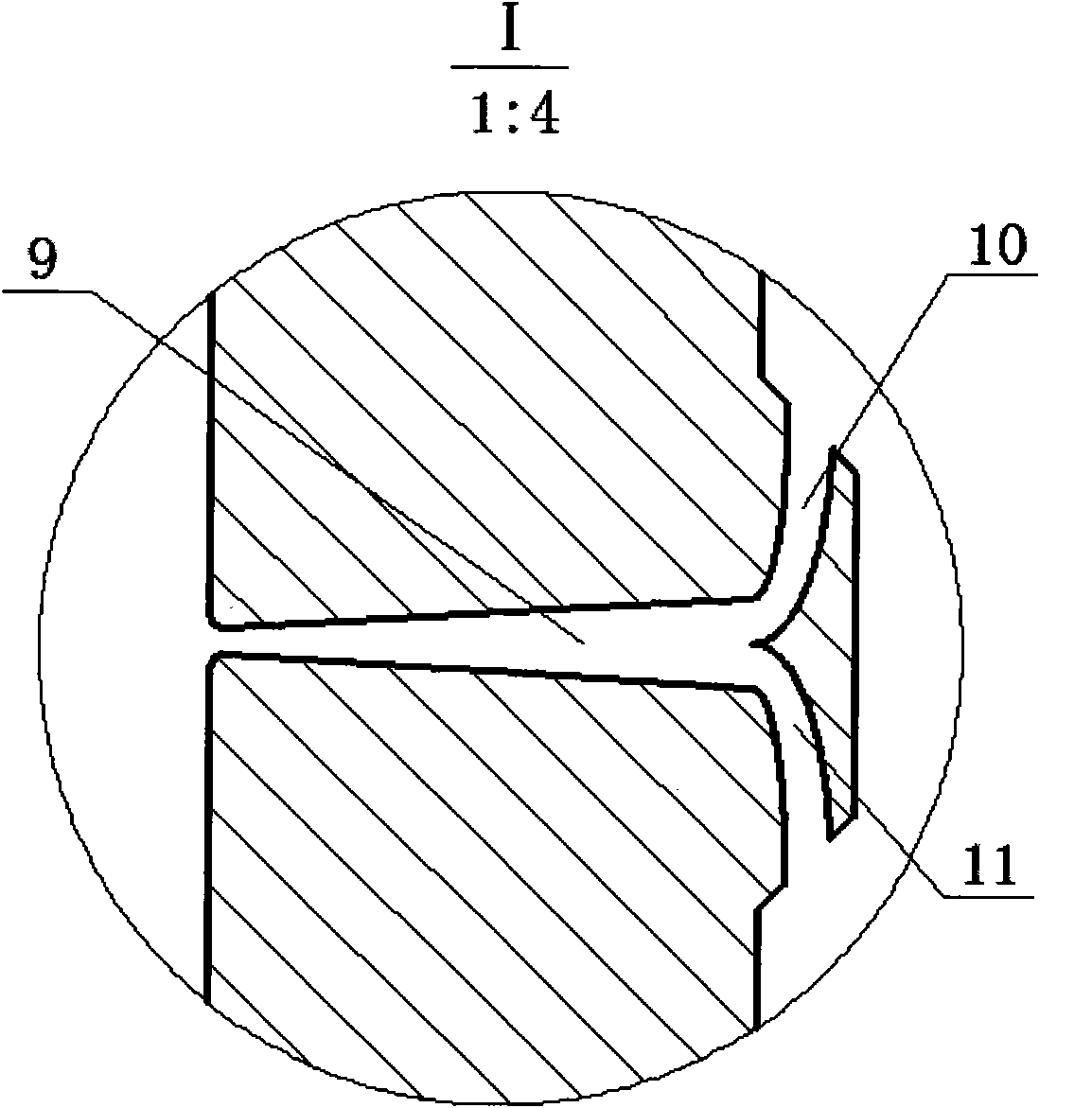
[0013] Such as Figure 1-3 , the present invention includes a pump body 8, a pump cover 2 and a piezoelectric vibrator 5, the pump body 8 and the pump cover 2 are electrostatically bonded together, and the piezoelectric vibrator 5 is fixed at the center of the lower part of the pump body 8 by an adhesive. A pump inlet 1 and a pump outlet 3 are processed on the pump cover 2, and the pump inlet 1 and the pump outlet 3 are externally connected with an inlet pipe and an outlet pipe respectively. Two inlet flow tubes 4, outlet flow tubes 7 and pump cavity 6 of the same structure are processed on the pump body 8 by using MEMS processing technology, wherein the pump cavity 6 is located between the inlet flow tube 4 and the outlet flow tube 7, and the inlet flow tube The pipe 4 and the outlet flow pipe 7 communicate with the pump chamber 6 respectively, and the three communicate with each other. The two inlet flow tubes 4 and outlet flow tubes 7 of the same structure are arranged coa...


PUM


Abstract

The invention discloses a valveless piezoelectric pump of an elliptical combined pipe, comprising a pump body, a pump cover and a piezoelectric vibrator, wherein the pump body is provided with an inlet flow pipe, an outlet flow pipe and a pump cavity; the inlet flow pipe and the outlet flow pipe have same structure and are coaxially arranged and equidistant from the center of the pump cavity; the inlet flow pipe and the outlet flow pipe respectively consist of a flow collecting conical pipe and two flow dividing elliptical pipes which are respectively communicated with the large end of the flow collecting conical pipe; the contour lines of the two flow dividing elliptical pipes are respectively formed by two coaxial elliptical line segments which have two coincided long and short axes and are different in length; the short half axis of the large ellipse is 450 mu m, and the long half axis thereof is 1200 mu m and is vertical to the central line of the flow collecting conical pipe; the starting point of the small elliptical line segment is positioned at the tail end of the large end surface of the flow collecting conical pipe, and the difference of the long half axes of the small ellipse is equal to the difference of the short half axes thereof; and the large ellipse is tangential to the central line of the flow collecting conical pipe, and the wrap angles of the two flow dividing elliptical pipes are respectively 60 degrees. The valveless piezoelectric pump has the advantages of small size, high flow resistance coefficient, good cavitation performance, no damage to the conveyed medium, capability of preventing electromagnetic interference and easier control of flow rate.

Description

technical field [0001] The invention relates to the field of microfluid transmission and control and micromechanical technology, in particular to a valveless piezoelectric pump. Background technique [0002] Piezoelectric pump is a kind of mechanical micropump, which belongs to positive displacement pump. It is widely used in the fields of micro-transportation of drugs, cell separation, cooling of electronic products (such as CPU), micro-injection of fuel, chemical micro-analysis, transition control in pipeline flow, etc. At present, piezoelectric pumps are mainly divided into two types: valve piezoelectric pumps and valveless piezoelectric pumps. The valved piezoelectric pump has a complex structure, is difficult to process, and is not suitable for working at a high frequency. The valveless piezoelectric pump has a simple structure, is more suitable for miniaturization and miniaturization, can meet the working requirements at high frequency, overcomes the shortcomings of t...

Claims


Application Information

Patent Timeline
Patent Type & Authority Applications(China)
IPC IPC(8): F04B43/04F04B53/00
Inventor 何秀华王健
Owner JIANGSU UNIV
Why Eureka
Try Eureka