
Spherical focal plane-based sub viewing field step gaze imaging optical system

An optical system, staring imaging technology, applied in optics, optical components, instruments, etc., can solve problems such as occlusion, achieve the effect of strong scalability, solve the large demand for device scale, and solve the difficulty of complex system integration

Inactive Publication Date: 2011-02-16
CHINA ACADEMY OF SPACE TECHNOLOGY
View PDF2 Cites 5 Cited by
  • Summary
  • Abstract
  • Description
  • Claims
  • Application Information

AI Technical Summary

Problems solved by technology

[0007] In order to overcome the deficiencies in the prior art, the present invention provides a sub-field of view step-by-step staring imaging optical system based on a spherical focal plane, which solves the technical problem of stepping and pointing the sub-field of view in the converging optical path, and avoids the Problems such as system occlusion caused by compressing parallel optical paths in the optical system provide a technical way for small-scale area array detectors to achieve large field of view and multi-channel staring imaging

Method used


Image

  • Spherical focal plane-based sub viewing field step gaze imaging optical system
  • Spherical focal plane-based sub viewing field step gaze imaging optical system
  • Spherical focal plane-based sub viewing field step gaze imaging optical system

Examples


Embodiment Construction

[0024] The present invention will be further described below in conjunction with accompanying drawing and specific embodiment:

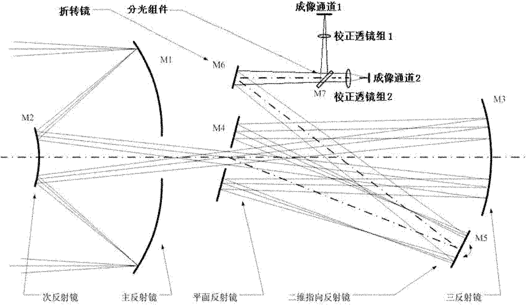
[0025] Such as figure 1 As shown, a sub-field of view step staring imaging optical system based on a spherical focal surface proposed by the present invention includes a front coaxial three-mirror main optical system, a two-dimensional pointing mirror system in the middle, a beam splitting component, and a rear The sub-field of view imaging channel correction lens group and the corresponding area array detector are combined.

[0026] The working principle of the entire optical system is: the target light enters the coaxial three-mirror main optical system, and reaches the two-dimensional pointing mirror system after four reflections; through the stepping motion of the pointing mirror, the light of each sub-field of view is introduced to the refracting mirror system one by one. The rotating mirror is reflected by it to the beam splitting component; a...


PUM


Abstract

The invention belongs to the technical field of optical remote sensing imaging, and relates to a spherical focal plane-based sub viewing field step gaze imaging optical system. The system aims to solve the problem of defocusing produced by sub viewing field step directing in a converging light path. A unique spherical focal plane form is adopted in the main optical system, a planar directing mirror is arranged in the converging light path, and the distance between the directing mirror and a main optical focal plane is accordant with the curvature radius of the spherical focal plane so as to avoid the problem of defocusing produced due to the motion of the directing mirror in the converging light path; and different sub viewing fields in a full viewing field are introduced into a subsequent imaging light path one by one by two-dimensional step directing of the directing mirror, the imaging light path is divided into different channels by a light splitting assembly, and a correction lens set of each imaging channel finishes focal length control and field curvature equal aberration correction to match the scale of a detection device in each channel and realize a flat image field required by the detection device. The system breaks through the technical bottleneck that the scale of a surface array detector in large surface array gaze imaging application is limited, and realizes scanning coverage of the full viewing field by using a small surface array detector.

Description

technical field [0001] The invention belongs to the technical field of optical remote sensing imaging, and relates to a sub-field of view step staring imaging optical system based on a spherical focal surface. Background technique [0002] In the field of optical remote sensing imaging, the requirements for large-scale wide staring imaging and multi-spectral composite imaging are getting higher and higher. The scale of the existing area array focal plane detectors is far from meeting the needs of practical applications, and has gradually become a bottleneck restricting the development of optical remote sensing imaging. . In order to solve the problem that the size of the area array detector is too small, the commonly used technical means at home and abroad include: area array detector splicing technology and sub-field step staring imaging technology. [0003] (1) Area array detector splicing technology [0004] There are many methods for splicing technology of area array d...

Claims


Application Information

Patent Timeline
IPC IPC(8): G02B27/10G02B17/06G02B26/10G02B27/00G01C11/02
Inventor 王世涛练敏隆王虎妹和涛邱民朴宋鹏飞
Owner CHINA ACADEMY OF SPACE TECHNOLOGY
Learn More