Unit test system

A unit testing and testing technology, applied in the field of general unit testing systems, can solve the problems of time-consuming developers, low overall framework reuse rate, cumbersome replacement and replacement, etc., to improve the quality of unit testing and easy to save results. Evaluate the effect of convenient interface development

Active Publication Date: 2011-02-16
ULTRAPOWER SOFTWARE
View PDF3 Cites 26 Cited by
  • Summary
  • Abstract
  • Description
  • Claims
  • Application Information

AI Technical Summary

Problems solved by technology

This is because when using these frameworks, developers not only need to spend a lot of time to understand the technical content, but also need to formulate test methods accordingly; moreover, if the test methods and standards are not rigorous enough, the entire test will be meaningless
[0005] In addition, the current unit test framework also has many problems: the interface is dry and difficult to use, and the development of the unit test graphical interface is not fast and convenient; the overall framework reuse rate is low, and it can only be used for one unit test, and it needs to be re-established in the next unit test Test framework; if a third-party unit test library is referenced, the entire framework will be closely linked to these test libraries, and its replacement and replacement will be very cumbersome; moreover, the existing third-party unit test library does not allow users to output information at will , which makes it impossible to generate perfect log files through the framework established by these test libraries, which reduces the credibility and traceability of unit tests; moreover, unit test results cannot be automatically saved, and testers need to complete them manually
The defect of the above solution is: since all the declarations and definitions are placed in the .h file, the dependence on it is too large, and the compilation speed is slow; and all the test .h files must be referenced by the file where the main function is located, resulting in compiles more slowly

Method used


Image

  • Unit test system
  • Unit test system

Examples


Embodiment Construction

[0031] The unit test system proposed by the present invention is described as follows in conjunction with the accompanying drawings and specific embodiments.

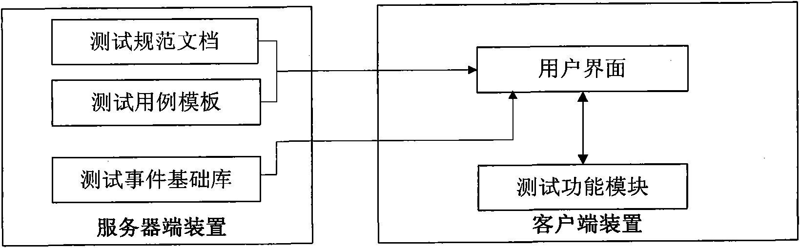
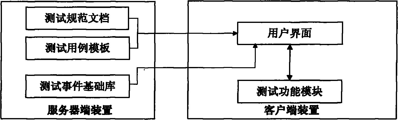
[0032] Such as figure 1 As shown, the unit test system of the present invention includes two parts, a server device and a client device connected through a computer network.

[0033] The server-side device according to the present invention is mainly used to generate and store unit test specification documents, test case templates and event base libraries for calling by the client-side device. The above-mentioned unit test specification document, test case template and event base library will be described in detail below in conjunction with specific embodiments.

[0034] Existing unit test frameworks generally only provide users with basic unit test library codes, so that users need to write their own corresponding unit test specifications in addition to using these codes as required, which not only increases the workl...


PUM


Abstract

The invention provides a unit test system which comprises a server end device and a client end device, wherein the server end device is connected with the client end device by a computer network; the server end device is used for generating and storing a test specification document, a test case template and a test event foundation library for calling the client end device; an event in the test event foundation library contains different information which is relevant to the test case executing condition in a packaging way, and the information is supplied to the client end device when the event is triggered; and the client end device is used for presenting the test specification document and the test case template for a user, compiling the test case document generated on the basis of the test case template by the user into a dynamic link library file and automatically filling a test result back to the corresponding position of the matched test case document by using a preset parameter as an index value. The system can realize accurate, rapid and high-quality unit test and prevent the influence of bug of a Visual Studio development environment on test case compiling.

Description

technical field [0001] The invention relates to the technical field of software testing, in particular to a general unit testing system. Background technique [0002] Unit testing is after the software development is completed, the developer writes the test code for the software code according to the conditions such as logic coverage, code coverage, initial value, critical value and expected value, to detect the correctness of the software code, thereby helping developers Find problems and improve software quality. [0003] There are two common unit testing methods at present. The first is free-style unit testing: the developer writes the unit test code, and determines the correctness of the code by comparing the expected value with the actual result; this method is purely based on the quality of the developer itself, without any normativeness, and it is difficult to make statistics. And it is difficult to evaluate the quality of the test code; at the same time, there are ...

Claims


Application Information

Patent Timeline
Patent Type & Authority Applications(China)
IPC IPC(8): G06F11/36
Inventor 张靖旻王桥
Owner ULTRAPOWER SOFTWARE
Why Eureka
Try Eureka