
Multi-variable air vibration noise reduction and elimination device and noise reduction and cancellation method

An air vibration, multi-variable technology, applied in the direction of sounding equipment, instruments, etc., can solve the problems of noise reduction and noise reduction troubled the public, the effect of noise reduction headphones is not good, and the application of noise reduction is limited, and it achieves good promotion value and low cost. , the effect of high energy conversion efficiency

Active Publication Date: 2012-06-27
SUZHOU BEIANG TECH LTD
View PDF4 Cites 0 Cited by
  • Summary
  • Abstract
  • Description
  • Claims
  • Application Information

AI Technical Summary

Problems solved by technology

But because the source of the noise comes from all directions: some directly enter the ear, some enter the human ear through reflection and refraction; in addition, the frequency of the noise varies greatly, and the vector direction of the noise injection is also different; The conversion structure must lag behind the noise by a phase (the size of the lagging phase depends on the material and thickness of the sound film medium), so that the effect of the current noise reduction headphones is not good, which seriously limits the application of noise reduction
[0003] In addition, the problem of noise reduction caused by air vibration outside the building or generated by electrical appliances has also been puzzling the public.
For example, Chinese patents CN03119467.2, CN200410058483.7, CN200710080149.5, CN200810006408.4, etc. also introduce some electronic systems that can actively eliminate noise, but these systems either have a small range of noise reduction, or have poor noise reduction effects

Method used

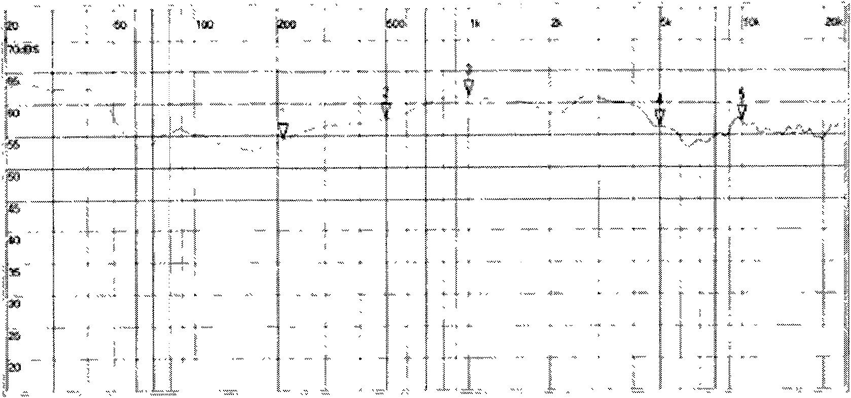
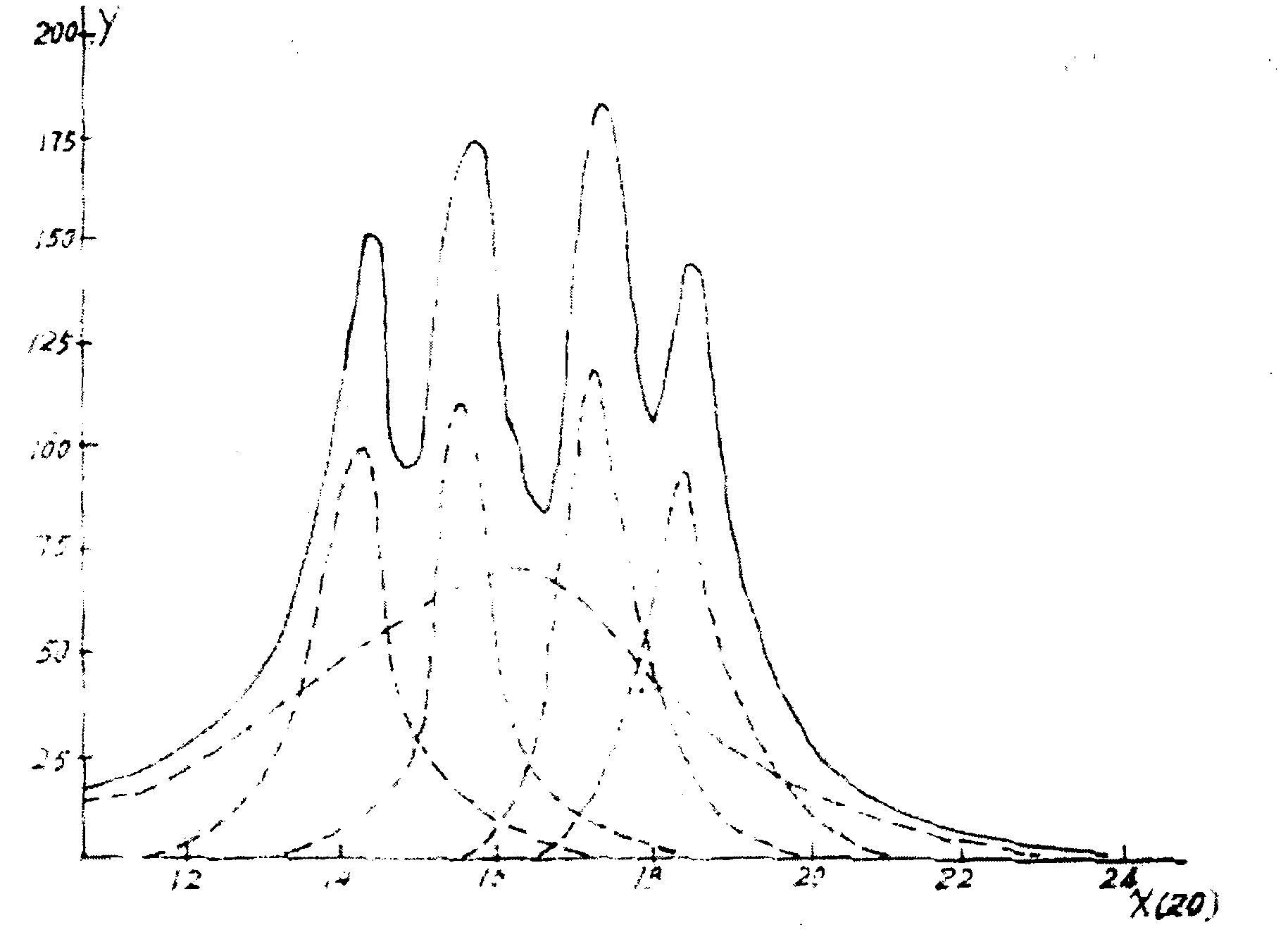

Image

  • Multi-variable air vibration noise reduction and elimination device and noise reduction and cancellation method
  • Multi-variable air vibration noise reduction and elimination device and noise reduction and cancellation method
  • Multi-variable air vibration noise reduction and elimination device and noise reduction and cancellation method

Examples


Embodiment Construction

[0031] The aforementioned and other technical contents, features and effects of the present invention will be clearly presented in the following detailed description of a preferred embodiment with reference to the drawings.

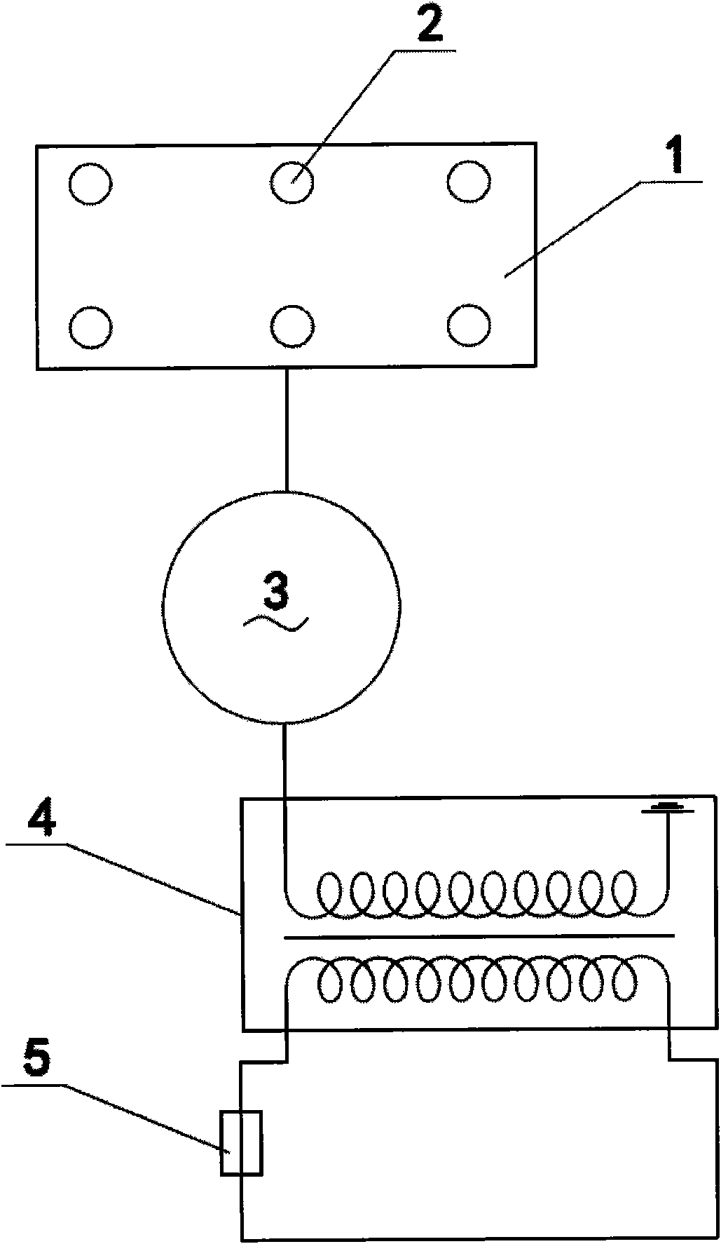
[0032] refer to figure 1 , Multi-variable air vibration noise reduction device, composed of an ion generating electrode pair 5, a high-voltage drive circuit 4, a noise collection analyzer 1, and an adjustable frequency anti-phase signal generator 3.

[0033] The positive electrode of the ion-generating electrode pair 5 is formed by winding an alloy wire equidistantly on an insulating wire frame, and the negative electrode is composed of a group of conductive flat plates, the plates are electrically connected to each other, and the positive and negative electrodes are connected to each other electrically. separated from each other by insulating columns.

[0034] A group of collection points 2 for collecting noise signals are evenly distributed on the surf...


PUM


Abstract

The invention discloses a noise reduction and elimination device for synthesizing a noise curve through mathematical solution and using ion wind as modulation power. The device comprises an ion electric field formed by a pair of electrodes, a noise acquisition analyzer, a high-pressure driving circuit and a reverse-phase signal generator for modulate frequency and amplitude. Under the action of the electric field power, plasmas generated by ionizing electrodes electrify air molecules to flow to further form ion wind because of an avalanche effect, and a vibration wave which has identical noise frequency and identical acting force with noise, but has opposite vector direction and opposite phase with noise is formed through the modulation of a frequency reverse-phase generator so as to reduce noise. The invention providing the device for reducing and eliminating noise in a larger range, having the advantages of extremely small distortion under different frequencies, low requirement for a frequency compensating circuit, lower cost, energy saving, emission reduction and optimal popularization values.

Description

technical field [0001] The invention relates to an air vibration noise reduction device. Background technique [0002] In order to drive away or reduce the noise in the air, the ion noise reduction device in the prior art generally needs a functional block capable of resisting the sound wave of the noise. This function block should be able to generate a group of sound waves equal in frequency and amplitude to the noise but opposite in vector direction. The current noise-cancelling headphones are developed based on this principle. But because the source of the noise comes from all directions: some directly enter the ear, some enter the human ear through reflection and refraction; in addition, the frequency of the noise varies greatly, and the vector direction of the noise injection is also different; The conversion structure must lag behind the noise by a phase (the size of the lagging phase depends on the material and thickness of the sound film medium), so that the curren...

Claims


Application Information

Patent Timeline
Patent Type & Authority Patents(China)
IPC IPC(8): G10K11/178
Inventor 陈竞坤科克兰陆衍陈竞芬刘义刚
Owner SUZHOU BEIANG TECH LTD
Learn More