Surface treatment method for filter cavity, cavity filter and communication apparatus

A cavity filter and surface treatment technology, which is applied in the field of communication, can solve the problems of high cost and the inability of connecting components to meet the requirements of corrosion resistance and wear resistance, and achieve the effect of meeting the requirements of corrosion resistance and wear resistance and reducing costs

Active Publication Date: 2011-02-16
ANHUI TATFOOK TECH CO LTD
View PDF3 Cites 0 Cited by
  • Summary
  • Abstract
  • Description
  • Claims
  • Application Information

AI Technical Summary

Problems solved by technology

[0006] In order to solve the problems in the prior art that the overall silver-plated material on the surface of the cavity filter leads to high cost, and the overall copper-plated material causes the connection components to fail to meet the ideal corrosion resistance and wear resistance requirements, the embodiment of the present invention discloses a filter filter A new idea of ​​the surface treatment method of the device cavity

Method used


Image

  • Surface treatment method for filter cavity, cavity filter and communication apparatus
  • Surface treatment method for filter cavity, cavity filter and communication apparatus
  • Surface treatment method for filter cavity, cavity filter and communication apparatus

Examples


Embodiment 1

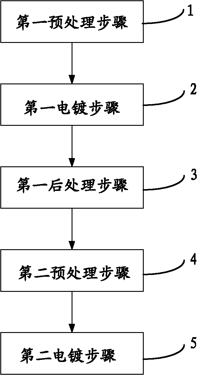
[0027] A surface treatment method for a filter cavity, the cavity filter includes a cavity and a connecting member integrally formed with the cavity, wherein the surface treatment method for the filter cavity includes the following steps:

[0028] A first electroplating step, in which the connecting member is shielded, and the cavity is plated with a first material so that the cavity meets the electrical performance requirements of the cavity filter; and

[0029] A second electroplating step. In the second electroplating step, the cavity is shielded, and the connecting member is electroplated with a second material, so that the connecting member meets the requirements for anti-corrosion and wear resistance.

[0030] The surface treatment method of the filter cavity provided in this embodiment performs different surface treatments for different parts of the cavity filter, and at the same time meets the electrical performance requirements of the cavity and the anti-corrosion and ...

Embodiment 2

[0032] A surface treatment method for a filter cavity. Please also see Figure 1 to Figure 5 ,in, figure 1 A simplified flowchart of a method for surface treatment of a filter cavity according to a preferred embodiment of the present invention is shown. The cavity filter provided in the embodiment of the present invention mainly includes a cavity 10 and a connecting member 20 integrally formed with the cavity 10. In this embodiment, the surface treatment method of the filter cavity includes the following steps in sequence:

[0033] Step 1: the first pretreatment step, in this step, including the sub-steps of acid degreasing, pickling, neutralization and galvanizing on the cavity 10 .

[0034] Step 2: the first electroplating step. In the first electroplating step, the connection member 20 is first shielded, and then the cavity 10 is electroplated with a first material, so that the cavity 10 meets the electrical performance requirements of the cavity filter. In this embodime...

Embodiment 3

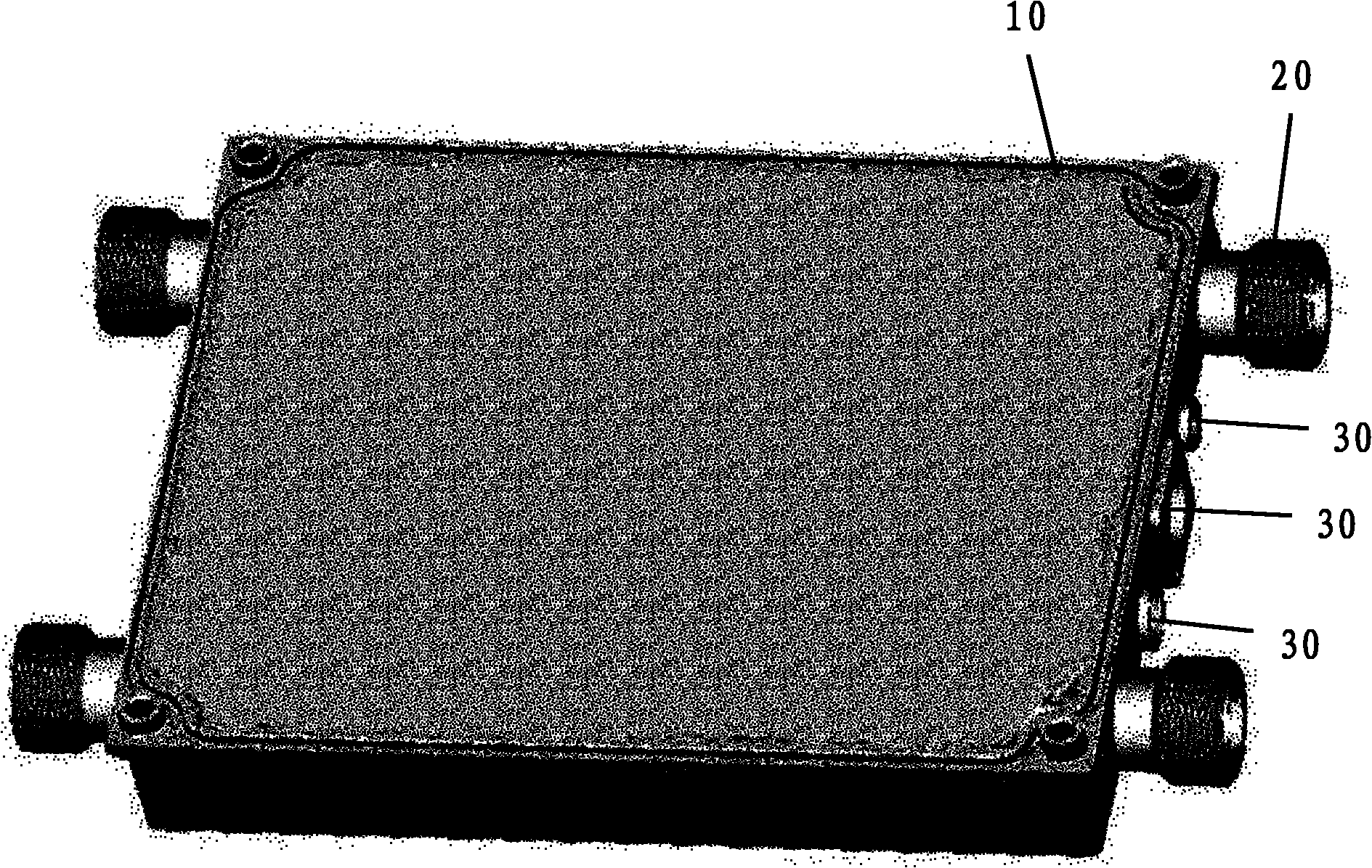
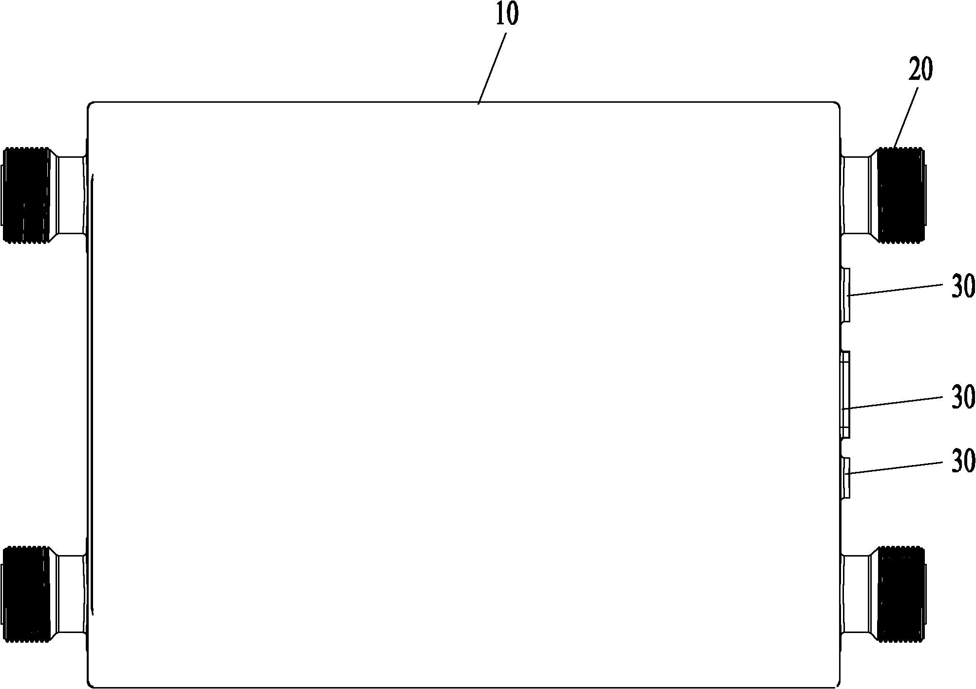
[0042] A cavity filter. Please also see Figure 2 to Figure 5 , which respectively show different views of the cavity filter according to the preferred embodiment of the present invention, the cavity filter provided according to the preferred embodiment of the present invention includes a cavity 10 and a connecting member 20 integrally formed with the cavity 10, The connecting member 20 is arranged on the side of the cavity 10, the connecting member 20 is provided with an inner hole communicating with the cavity 10, and the side wall of the cavity 10 is further provided with a plurality of special connecting holes 30, of course, the connecting member The positions of 20 and the plurality of dedicated connecting holes 30 are not limited to those shown in the drawings. Of course, the cavity filter provided by the embodiment of the present invention also includes various other conventional components or structures. Here, this embodiment only describes the parts related to the in...


PUM


Abstract

The embodiment of the invention discloses a surface treatment method for a cavity of a cavity filter. The cavity filter comprises a cavity and a connecting component which is integrally formed with the cavity. The surface treatment method for a filter cavity comprises a first electroplating step and a second electroplating step, wherein in the first electroplating step, shielding the connecting component, and electroplating the first material on the cavity, so that the cavity satisfies the electrical property requirements of the cavity filter; and in the second electroplating step, shielding the cavity, electroplating the second material on the connecting component, so that the connecting component satisfies the requirements for corrosion resistance and abrasion resistance. In addition, the embodiment of the invention also discloses a cavity filter and a communication apparatus using the cavity filter. The embodiment of the invention discloses a novel way of thinking for surface treatment methods for filter cavities, can enhance the corrosion resistance and abrasion resistance, and can lower the processing cost.

Description

【Technical field】 [0001] The invention relates to cavity filter technology in the communication field, in particular to a surface treatment method for a filter cavity, a cavity filter and communication equipment. 【Background technique】 [0002] The cavity filter is widely used in the communication field as a frequency selection device. Due to the special requirements of the cavity filter on the conductivity of the cavity, the surface of the cavity must be electroplated. [0003] Electroplating is a process of plating a thin layer of other metals or alloys on some metal surfaces by using the principle of electrolysis. Electroplating can prevent corrosion, improve wear resistance, conductivity, reflectivity and enhance aesthetics. [0004] The cavity filter mainly includes a cavity and connecting components arranged on the side of the cavity. In the prior art, in order to improve the performance of the cavity filter while reducing the cost, a new cavity structure is to integr...

Claims


Application Information

Patent Timeline
Patent Type & Authority Applications(China)
IPC IPC(8): H01P1/207H01P11/00
Inventor 孙尚传童恩东邵聪刘长亮汪心祥
Owner ANHUI TATFOOK TECH CO LTD
Why Eureka
Try Eureka