Motor

A motor and armature technology, which is applied in the field of electric motors, can solve the problems of reduction of motor rotation torque and electromotive force, and achieve the effect of reducing cogging torque and inhibiting the reduction of rotation torque.

Inactive Publication Date: 2011-02-16
NIDEC CORP
View PDF8 Cites 12 Cited by
  • Summary
  • Abstract
  • Description
  • Claims
  • Application Information

AI Technical Summary

Problems solved by technology

As a result, the electromotive force generated with the rotation of the rotating body is greatly reduced, and the rotational torque of the motor is reduced.

Method used


Image

  • Motor
  • Motor
  • Motor

Examples


Embodiment approach

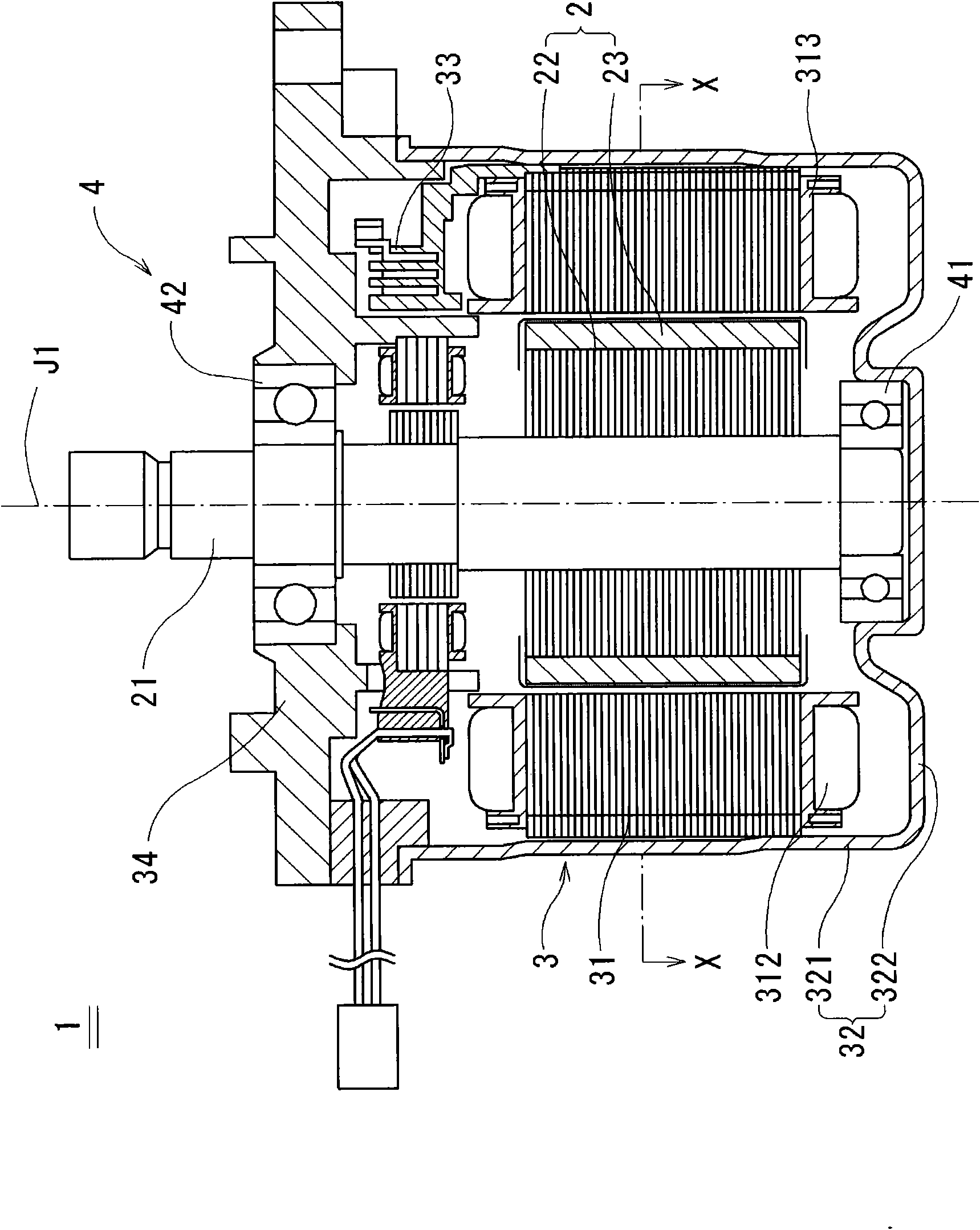
[0027] figure 1 It is a cross-sectional view schematically showing the motor 1 according to the first preferred embodiment of the present invention. Such as figure 1 As shown, the motor 1 has a rotating body 2 , a fixed body 3 and a bearing mechanism 4 . The rotating body 2 has a rotor magnet 23 composed of permanent magnets having a substantially annular shape centering on the central axis J1. The fixed body 3 has an armature 31 disposed radially opposite to the rotor magnet 23 . The bearing mechanism 4 supports the rotating body 2 such that the rotating body 2 can rotate about the central axis J1 relative to the fixed body 3 . The motor 1 of this embodiment is a three-phase brushless motor. Furthermore, the electric motor 1 of the present embodiment is mounted on an electric power steering device. Accordingly, it is possible to provide an electric power steering device that achieves a low cogging torque and achieves miniaturization.

[0028] The rotating body 2 has a s...


PUM


Abstract

A protrusion (50) is arranged on an opposing surface (319) of a teeth portion (315) to protrude toward a rotor magnet (23). The protrusion (50) is arranged substantially at the center of the opposing surface (319) in the circumferential direction. Thus, the fundamental wave of the waveform of a cogging torque generated by the slot opening (320) has a phase inverse to the phase of the waveform of a cogging torque generated by the protrusion (50). Thus, the cogging torque generated by the slot opening (320) is reduced by the cogging torque generated by the protrusion (50).

Description

technical field [0001] The present invention relates to electric motors. Background technique [0002] In recent years, an electric power steering device has been developed in which a drive source of the power steering device that assists the operation of the steering wheel is replaced from a hydraulic pressure to an electric motor. By replacing the hydraulic power steering with an electric power steering, the fuel consumption of the vehicle can be increased by several percent. [0003] The electric power steering system seeks a technology that does not transmit the vibration of the electric motor to the steering wheel so that the operator who operates the steering wheel does not feel uncomfortable. Therefore, various motors have been developed that reduce cogging torque, which is one of the sources of motor vibration (for example, JP-A-2003-61272). [0004] In addition, with the electrification of vehicles, many electronic components are mounted on vehicles compared with ...

Claims


Application Information

Patent Timeline
Patent Type & Authority Applications(China)
IPC IPC(8): H02K21/16H02K1/16H02K1/27H02K21/14
CPCH02K21/16H02K1/148H02K29/03
Inventor 见城尚志片冈央内谷良裕山下佳明
Owner NIDEC CORP
Why Eureka
Try Eureka