Automatic magnetic roller paint spraying equipment

An automatic painting and magnetic roller technology, applied in the direction of spraying devices, etc., can solve the problems of complex operation, low efficiency, and unguaranteed spraying quality, and achieve the effect of simple equipment structure, convenient operation, and reliable spraying performance

CN101979151AInactive Publication Date: 2011-02-23FOREVER TECH
4 Cites 12 Cited by

Patent Information

Authority / Receiving Office
CN · China
Current Assignee / Owner
Publication Date
2011-02-23
Estimated Expiration
Not applicable · inactive patent

Smart Images

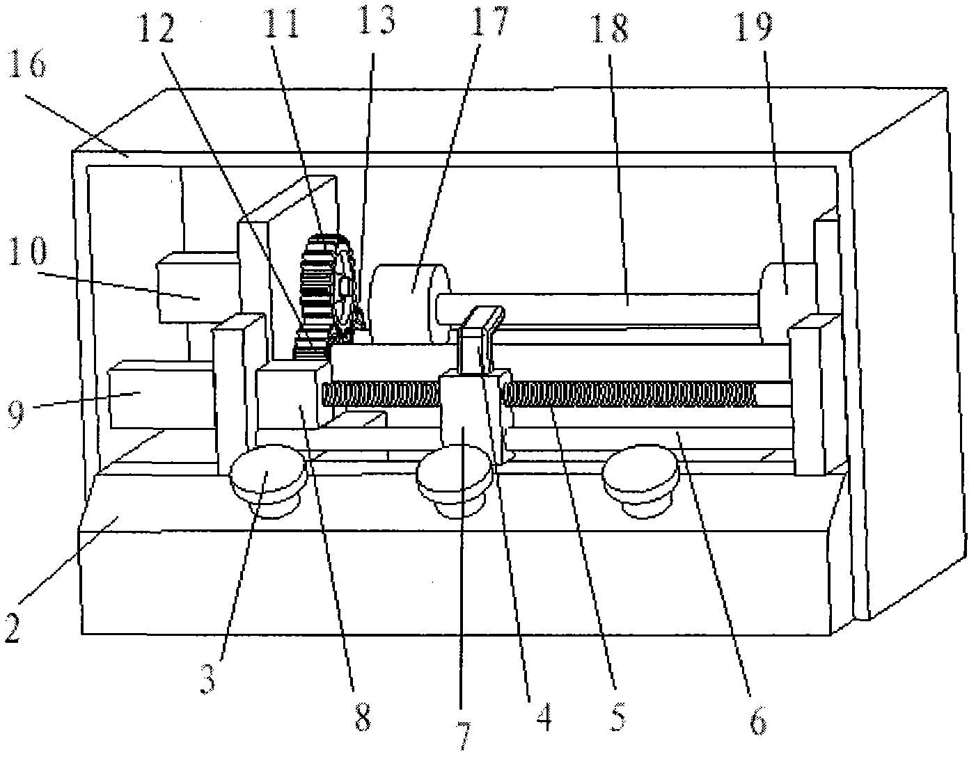
  • Figure 1
    Figure 1
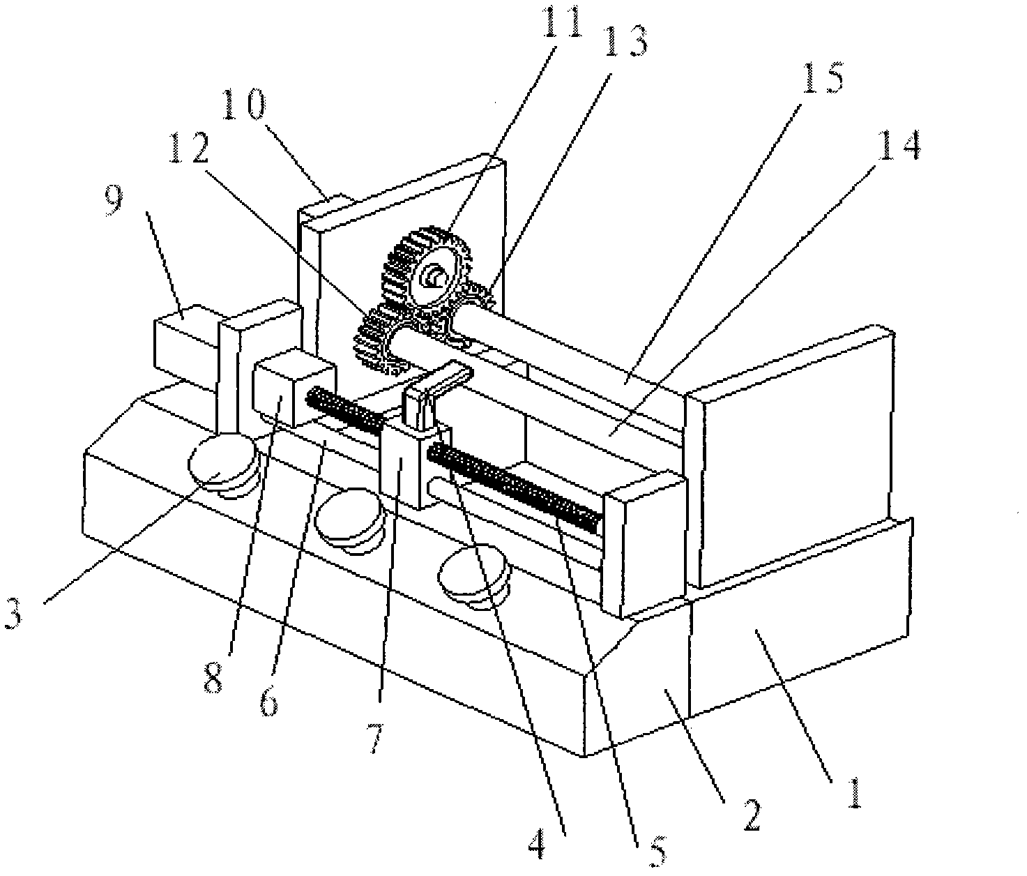
  • Figure 2
    Figure 2
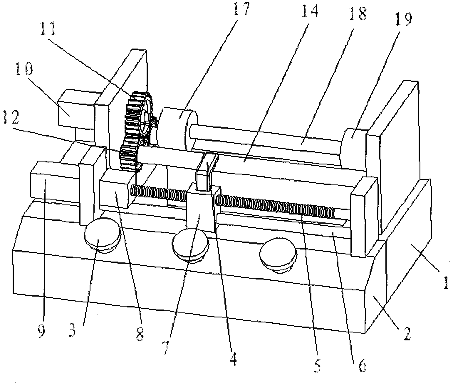
  • Figure 3
    Figure 3
Patent Text Reader

Abstract

The invention relates to automatic magnetic roller paint spraying equipment. The equipment consists of a base, a water screen spraying cabinet, a magnetic roller power transmission system, a spray gun moving device and an electrical appliance control cabinet, wherein the water screen spraying cabinet is a cabinet body of which the right side is provided with an opening; the inner wall of the cabinet body is used as a water screen plate; the cabinet body and the base enclose a water tank; water flow outflowing from a water pump arranged above the cabinet body forms a water screen to adsorb sprayed paint; the electrical appliance control cabinet abuts against the spray gun moving device and is arranged in parallel on the outer side of the water screen plate to control the operation of the equipment; in the magnetic roller power transmission system, power is outputted by a motor, and two rotating shafts are driven to rotate in the same direction through the meshing transmission of a gear so as to realize the rotation of a magnetic roller; and in the spray gun moving device, the power is outputted by a servo motor, and a lead screw is driven to rotate by a coupler, so that a spraying gun fixed on a lead screw nut block moves right and left. In the automatic paint spraying equipment, the motor does not need stopping in the process of replacing the magnetic roller, so that the automatic magnetic roller paint spraying equipment has a simple structure, is convenient to operate, has reliable spraying performance, and improves the efficiency greatly.
Need to check novelty before this filing date? Find Prior Art

Description

Technical field

[0001] The invention relates to a painting equipment for cylindrical workpieces, and is particularly suitable for automatic painting equipment for magnetic rollers in the toner cartridge industry.

Background technique

[0002] The magnetic roller is one of the key components in the toner cartridge assembly. Its quality determines the printing quality, and the surface roughness of the magnetic roller is also a determinant of the quality of the toner cartridge; Sandblasting, after sandblasting, paint the surface again to change the roughness and surface quality of the magnetic roller.

[0003] In the prior art, manual spraying and machine spraying equipment are mainly used to spray paint on the magnetic roller, but manual spraying is affected by proficiency, and the quality of spraying cannot be guaranteed, while most machine spraying equipment uses a motor to directly drive the magnetic roller to rotate. The motor needs to be stopped when the magnetic rol...

Examples

Embodiment Construction

[0014] see figure 1 , 2,3 An automatic inflation device for an inflatable bag, the device consists of a base (1), a water curtain spray cabinet (16), a magnetic roller power transmission system, a spray gun moving device and an electrical control cabinet (2).

[0015] The magnetic roller power transmission system and the spray gun moving device are installed in parallel on the base (1), and are arranged inside the water curtain spraying cabinet (16). The electrical control cabinet (2) is placed in parallel with the spray gun moving device in the water curtain spraying cabinet (16 ) outside; the motor (10) in the magnetic roller power transmission system is installed on the support of the base (1), and the large gear (11) is installed on the motor (10) main shaft, and on the support of the motor (10), the motor ( 10) On both sides of the main shaft, install shaft I (14) and shaft II (15) parallel to the axis of the motor shaft. Two pinion gears I (12) are arranged on shaft I (1...