Spray desuperheater

A water spray desuperheating and desuperheater technology, which is applied in the control of superheat temperature, steam superheating, steam generation, etc., can solve the problems of large volume, complex manufacturing process and low heat exchange efficiency.

Inactive Publication Date: 2011-02-23
FEICHENG BAIZHUANG COAL MINE +2
View PDF8 Cites 5 Cited by
  • Summary
  • Abstract
  • Description
  • Claims
  • Application Information

AI Technical Summary

Problems solved by technology

[0003] There are mainly two types of desuperheaters: non-contact type and direct contact type. Due to the disadvantages of non-contact type such as low heat transfer efficiency, large volume, and waste of cooling water, direct contact type desuperheaters that achieve cooling by spraying water are mostly used at present. , the direct contact desuperheater cools down through direct contact between cooling water and 
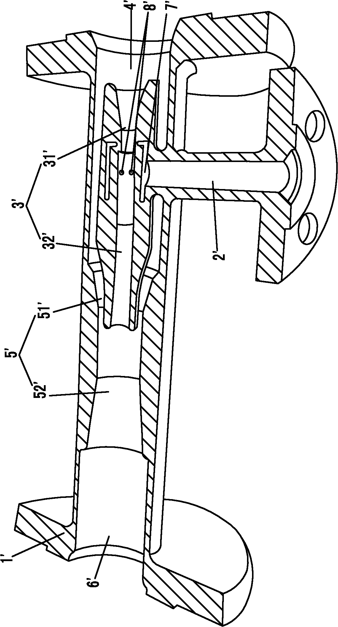
superheated steam, that is, spraying water for desuperheating, such as figure 1 The structure diagram of the existing desuperheater is shown, which is composed of a horizontally placed desuperheating water pipe 1', a first-stage venturi tube 3' placed in the inner cavity of the desuperheating water pipe 1', and a vertically placed cooling water pipe 2'. , the cooling water pipe 2' vertically passes through the desuperheating water pipe 1' and the first-stage Venturi pipe 3', and the desuperheating water pipe 1' is successively connected by the superheated steam inlet port 4', the second-stage Venturi pipe 5' and The superheated steam outlet port 6' is formed, and the flaring section 32' on the left part of the first-stage Venturi tube 3' is arranged between the flaring section 52' and the constricting section 51' of the inner cavity of the second-stage Venturi tube 5' At the throat of the first-stage Venturi tube 3', the necking section 31' on the right part is set in the inner cavity of the superheated steam inlet port 4', the first-stage Venturi tube 3' and the second-stage Venturi tube 5' The inner cavity of the first-stage Venturi tube 3' is connected with the necking section 31' and the flaring section 32' at the junction of the first-stage Venturi tube 3'. ' communicates with the inner cavity of the cooling water pipe 2', the desuperheater adopts a two-stage Venturi tube, and the cooling water flows from the cooling water pipe 2' through the first-stage Venturi tube 3' through the groove 7' and the outlet hole 8' Flowing into the inner cavity of the first-stage Venturi tube 3', after the superheated steam enters the first-stage Venturi tube 3', the gas flow changes from thick to thin, and the gas flow speed is accelerated, so that the gas flows through the throat of the first-stage Venturi tube 3'. A negative pressure area is formed below the mouth, and the cooling water outlet hole 8' is in this negative pressure area, and the negative pressure produces a certain suction effect on the cooling water, so that the negative pressure area below the throat of the first-stage Venturi tube 3' The cooling water flows into the inner cavity of the first-stage Venturi tube 3', the cooling water is atomized for the first time, and mixed with the superheated steam coming in from the superheated steam inlet port 4' at the right end, and the first-stage Venturi tube 3' The mixed steam that comes out directly enters the throat of the second-stage Venturi tube 5', and uses the high-speed gas at the throat of the second-stage Venturi tube 5' to perform a second Secondary atomization, mixed with superheated steam again, then flows out of desuperheater from superheated steam outlet 6'
[0004] The disadvantage of this structure is that the manufacturing process is complicated and the pressure and flow of the superheated steam flowing into the desuperheater must be stable enough. If the pressure and flow of the superheated steam are small, the two-stage venturi tube cannot form sufficient suction force, and the desuperheater The cooling effect of the desuperheater is poor, and the cooling effect of the desuperheater is related to the load change, that is, when the pressure and flow of the superheated steam are unstable, the jet atomization effect of the Venturi tube is poor, and the temperature and pressure of the steam after the desuperheater is cooled are also unstable.

Method used


Image

  • Spray desuperheater
  • Spray desuperheater
  • Spray desuperheater

Examples


Embodiment Construction

[0012] see figure 2 As shown, the spray desuperheater of the present invention includes a tubular desuperheater header 1, an inner sleeve 2, a first-stage Venturi tube 3, a second-stage Venturi tube 4, a cooling water pipe 5 and an L-shaped centrifugal Nozzle 6;

[0013] The inner sleeve 2 is sleeved in the inner cavity of the desuperheater header 1, the first-stage Venturi tube 3 and the second-stage Venturi tube 4 are sleeved in the inner cavity of the inner sleeve 2, and the first-stage Venturi tube 3 It is composed of the necking section 31 on the left and the flared section 32 on the right. The second-stage Venturi tube 4 is composed of the necking section 41 on the left and the flared section 42 on the right. The first-stage Venturi tube 3 The right end of the flaring section 32 on the right extends from the left end of the second-stage Venturi tube 4 into the throat cavity of the second-stage Venturi tube 4;

[0014] The cooling water pipe 5 vertically passes through...


PUM


Abstract

The invention discloses a spray desuperheater, which belongs to the field of boiler plants. The spray desuperheater comprises a tubular desuperheater header and the like. An inner sleeve is sleeved to a cavity of the desuperheater header. A primary venturi tube and a secondary venturi tube are arranged in the cavity of the inner sleeve, wherein the flared section of the primary venturi tube enters the cavity at the throat of the secondary venturi tube from the left end of the secondary venturi tube. A cooling water pipe vertically runs through the desuperheater header and the inner sleeve; the lower end of the cooling water pipe is connected with an upper end at the throat of the primary venturi tube; and the cavity of the cooling water pipe is communicated with that of the primary venturi tube. The lower end of a centrifugal nozzle runs through the cooling water pipe and then is extended into the cavity of the primary venturi tube; and the spray directions of spray orifices at the lower end of the centrifugal nozzle are dead against the secondary venturi tube. Due to the combination of the centrifugal nozzle and the primary and secondary venturi tubes, the spray desuperheater solves the problem of small atomization range and poor heat exchange effect of desuperheating water, is simple to machine, and can highly-efficiently atomize the desuperheating water in large scale to further effectively improve the heat exchange performance of the desuperheater.

Description

technical field [0001] The invention relates to boiler equipment, in particular to a water spray desuperheater. Background technique [0002] The desuperheater is an important device used to adjust the steam temperature. In a thermal power plant, the boiler produces a large amount of superheated steam. If the desuperheater is not equipped, it will be difficult to control the temperature of the boiler outlet steam within the required range. Boiler steam turbine related equipment is damaged or caused a major accident due to over-temperature. When the steam temperature cannot meet the requirements of the steam turbine, the superheated steam must be desuperheated through the desuperheater. [0003] There are mainly two types of desuperheaters: non-contact type and direct contact type. Due to the disadvantages of non-contact type such as low heat transfer efficiency, large volume, and waste of cooling water, direct contact type desuperheaters that achieve cooling by spraying wate...

Claims


Application Information

Patent Timeline
Patent Type & Authority Applications(China)
IPC IPC(8): F22G5/12
Inventor 赵树平李军程栾庆杨平陈崇柱彭延生韩学义张鹏彭民张贞元曹茂永王毅范迪程学珍
Owner FEICHENG BAIZHUANG COAL MINE
Why Eureka
Try Eureka