Adjustable heat collecting device for rotary kiln body

A collection device and rotary kiln technology, which is applied in rotary drum furnaces, waste heat treatment, lighting and heating equipment, etc., can solve the problems of heat energy not being well utilized, useless heat recovery and efficiency decline, etc., so as to achieve recycling and utilization. The effect of reducing the energy consumption of equipment, short payback period and reducing equipment energy consumption

Active Publication Date: 2011-02-23
NANJING KESEN KENEN ENVIRONMENT & ENERGY
View PDF3 Cites 10 Cited by
  • Summary
  • Abstract
  • Description
  • Claims
  • Application Information

AI Technical Summary

Problems solved by technology

At present, this part of heat is basically useless and can be recycled. Even if there is a small amount of utilization, there are various limitations.
[0004] First of all, after installing the heat collecting device, the heat dissipation of the rotary kiln carcass is reduced, and the surface temperature of the kiln rises to a certain extent. A large rise may reach or exceed the limit temperature, which will affect the safety and life of the cement kiln; secondly, when the heat consumption of the heat user is reduced, the collected heat will be dissipated in vain, and the operation and maintenance consumption will not be reduced, and the heat dissipation may be accompanied by soda The loss of working fluid leads to a decline in efficiency; again, in order to ensure that the kiln body does not exceed the temperature, the usual practice is to reduce the collected heat, that is, the heat energy that can be used is far from being well utilized
Due to the above reasons, its use and promotion are restricted. At present, there are only a small number of units collecting heat dissipation, which are only used for heating and hot water supply, and are idle in non-heating seasons.

Method used


Image

  • Adjustable heat collecting device for rotary kiln body
  • Adjustable heat collecting device for rotary kiln body
  • Adjustable heat collecting device for rotary kiln body

Examples


Embodiment Construction

[0013] The present invention will be described in further detail below in conjunction with the accompanying drawings and embodiments.

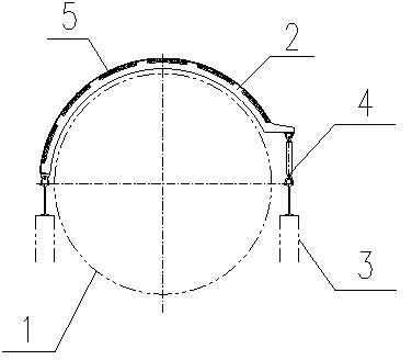
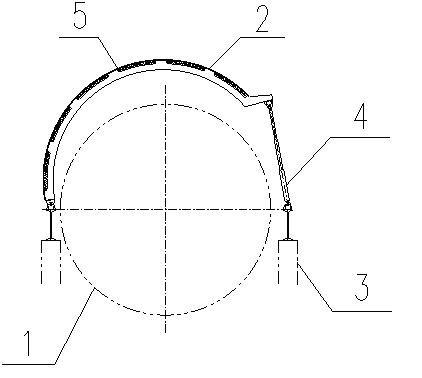
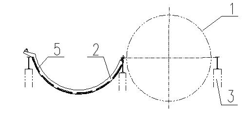
[0014] Such as figure 1 and 2 As shown, the heat collection unit is composed of a heat collection cover 2 , a bracket 3 and a position adjustment system 4 . Two brackets 3 are installed on both sides of the carcass of the rotary kiln 1, one of the brackets 3 is directly connected to the heat collecting cover 2, and the other bracket 3 supports the heat collecting cover 2 through the position adjustment system 4, and the heat collecting cover 2 is controlled by the heating surface 5 , thermal insulation material and fixed material, the change of the heat collected by the heat collecting unit can be realized by adjusting the whole device.

[0015] Among them, the position adjustment system 4 is composed of a support mechanism and an actuator, and the actuator is a telescopic device. The telescopic actuator can be a wire sleeve, that is, the ou...


PUM


Abstract

The invention relates to an adjustable heat collecting device for collecting heat dissipated by a rotary kiln body. The device is formed by connecting a plurality of independent heat collection units, wherein each heat collection unit comprises a heat collecting cover, a bracket and a position adjusting system; the heat collecting cover comprises a heated surface, a heat preserving material, a frame, a protective shield and the like; brackets are arranged on two sides of the rotary kiln body, the brackets on one side are directly connected with heat collecting shields, while the position adjusting systems are arranged between the brackets on the other side and the heat collecting covers; and each position adjusting system consists of a support mechanism and an execution mechanism. The heat collected from the rotary kiln body and the temperature of a heating working medium can be adjusted through the change of positions of the heat collection units, the connecting assembly way between the units of the heat collecting device and the change of the number of switching so as to ensure that the reclaimed heat and the surface temperature of the rotary kiln body are in a safe range, guarantee safe operation of the rotary kiln, and realize harmonization and unification of equipment safety, operation economy and heat reclaiming maximization.

Description

technical field [0001] The invention relates to a heat collecting device, in particular to a collecting device for recovering the heat dissipation of a rotary kiln carcass. Background technique [0002] At present, the international and domestic vigorously promote energy conservation and emission reduction, carry out clean production, and develop a low-carbon economy. The Chinese government promises that by 2020, the energy consumption per unit of GDP in my country will be reduced by 40-45%. The task of energy conservation and emission reduction is arduous. [0003] In recent years, the cement industry has developed rapidly, and my country's cement output has exceeded half of the world's output. The cement industry is a high-energy-consuming industry. The recovery of waste heat from cement kilns is one of the key energy-saving projects in the "Eleventh Five-Year Plan" of the country. At present, the recovered waste heat is mainly the heat of waste gas at the kiln head and ki...

Claims


Application Information

Patent Timeline
Patent Type & Authority Applications(China)
IPC IPC(8): F27B7/20F27D17/00
CPCY02P10/25
Inventor 王暐谢奕敏王建立刘亚雷王化雨何张陈
Owner NANJING KESEN KENEN ENVIRONMENT & ENERGY
Why Eureka
Try Eureka