Process for testing capacitance type touch screen

A capacitive touch screen and touch screen testing technology, applied in the direction of measuring electricity, measuring devices, measuring electrical variables, etc., can solve the problems of low test efficiency, not directly giving good and bad products judgment, not suitable for mass production, etc., to achieve test efficiency. High, improve the effect of test accuracy and work efficiency

Inactive Publication Date: 2011-03-02
TIANJIN ZHONGHUAN HI TECH
View PDF5 Cites 38 Cited by
  • Summary
  • Abstract
  • Description
  • Claims
  • Application Information

AI Technical Summary

Problems solved by technology

[0003] Method 1 adopts the method of two-point simulation test. The test position cannot cover the entire touch range, but only simulates the two key points, and cannot fully detect all ITO film patterns and silver lines;
[0004] The second method is to use circuit board chip testing method, which is to conduct statistical analysis on the parameter consistency of the developed and tested products, and does not directly give the judgment of good and bad products, but judges good and bad products based on the statistical analysis results, which is not suitable for mass production;
[0005] The third method is to use the installation test. This method is more complicated. The advantage is that the test is more intuitive and the test effect is better. The disadvantage is that if there are defective products in the installation test, it needs to be disassembled and replaced, which increases the working hours and affects the production progress;
[0006] Method 4: It is more intuitive to use the product linearity tester to test, and the test effect is better, but the test speed is slow, and all batch products need to be tested. The test efficiency of this method is low

Method used


Image

  • Process for testing capacitance type touch screen
  • Process for testing capacitance type touch screen
  • Process for testing capacitance type touch screen

Examples


Embodiment Construction

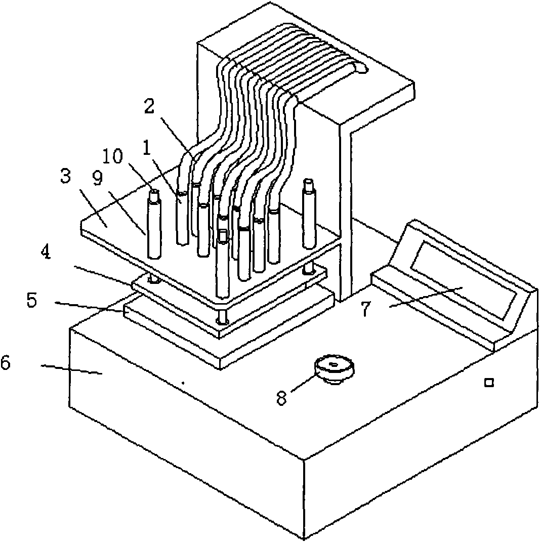
[0018] Such as Figure 1 to Figure 3 As shown, the touch screen tester includes a test chip circuit controlled by a single-chip microcomputer, an instrument casing 6, a pneumatic touch head 1, an air pipe 2, a touch head frame 3, a touch head movable fixture 4, and a touch screen test interface board 5;

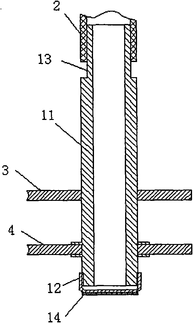
[0019] The pneumatic touch head 1 is composed of a metal tube 11 and a thin metal disc cap 12. The thread at the lower end of the metal tube 11 is screwed into the thin metal disc cap 12. A layer of conductive rubber 14 is pasted on the surface of the thin metal disc cap 12. The end of the metal tube 11 is The upper part processes the trachea interface 13, and the trachea 2 is plugged on the trachea interface 13, and the diameter of the trachea interface 13 is closely matched with the trachea 2 inner diameter.

[0020] The instrument case 6 is the support body of the touch head frame 3, and the lower end parts of the metal tubes 11 of 12 pneumatic touch heads pass through the...


PUM


Abstract

The invention relates a capacitance type touch screen testing process by simulating a human hand to touch a touch screen of a mobile phone by multiple points. The process adopts the method of simulating the human hand to touch the touch screen of the mobile phone by multiple points, and multipoint simulated human hand touch action is completed by a special touch screen tester, so that points to be tested cover the effective range of the whole screen. Before testing, a thin metal plate cap of a pneumatic touch head is in a non-stressed state, the thin metal plate cap maintains a normal-state shape, at the moment, the pneumatic touch head and a detected point of the touch screen are in clearance contact; when testing, an air pipe is connected with an air source, under the action of air pressure, the thin metal plate cap is elastically deformed to protrude downwards, the conductive rubber on the surface of the thin metal plate cap simulates fingers of the human hand to press the detected point of the touch screen; when the air source is cut by the air pipe, the thin metal plate cap is recovered to the normal-state shape; and a test chip circuit is connected with a capacitor of the detected point of the touch screen, and a singlechip determines the touch position by measuring capacitor changes and acquires capacitor changing information.

Description

technical field [0001] The invention relates to an electrical property testing process of a touch screen, in particular to a capacitive touch screen testing process for testing by adopting multi-point simulation of the condition of human hands touching the touch screen of a mobile phone. Background technique [0002] At present, there are usually four test methods for mobile phone touch screens: 1. Two-point simulation test, 2. Circuit board chip test, 3. Installation test, 4. Product linearity test. [0003] Method 1 adopts the method of two-point simulation test. The test position cannot cover the entire touch range, but only simulates the two key points, and cannot fully detect all ITO film patterns and silver lines; [0004] The second method is to use circuit board chip testing method, which is to conduct statistical analysis on the parameter consistency of the developed and tested products, and does not directly give the judgment of good and bad products, but judges go...

Claims


Application Information

Patent Timeline
Patent Type & Authority Applications(China)
IPC IPC(8): G01R31/00G06F3/044
Inventor 王宪结王瑞霞马颖
Owner TIANJIN ZHONGHUAN HI TECH
Why Eureka
Try Eureka