Annular pipe reactor
A loop reactor and reaction technology, applied in chemical instruments and methods, chemical/physical/physicochemical processes, chemical/physical processes, etc., can solve the problem of reducing the heat transfer efficiency of cooling medium and the poor heat transfer effect of loop reactors , impact and other issues
- Summary
- Abstract
- Description
- Claims
- Application Information
AI Technical Summary
Problems solved by technology
Method used
Image
Examples
Embodiment 1
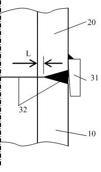
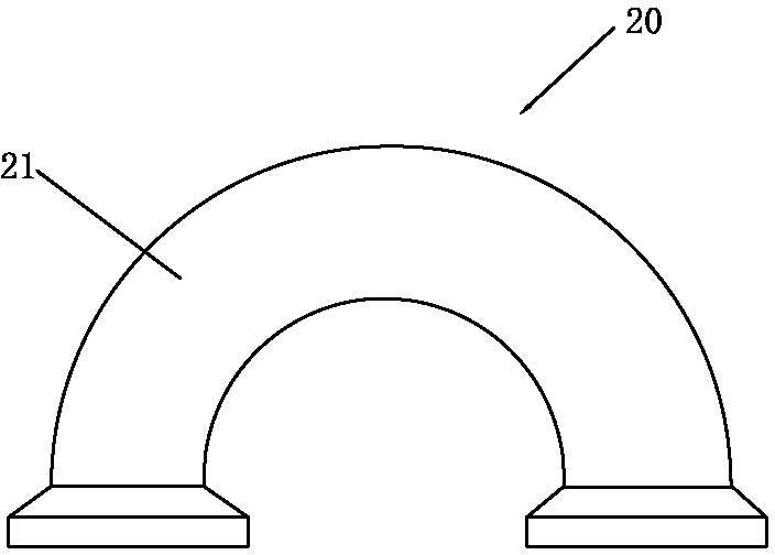
[0046] One of the specific implementations of a loop reactor of the present invention, such as figure 2 As shown, it includes a straight bushing 10, a jacket connecting pipe, an elbow 20 and an installation support. The straight bushing 10 includes an inner tube 11 and an outer tube 12. The end of the elbow 20 and the end of the inner tube 11 Connect in series in turn, and connect the straight sleeve 10 into a communication flow channel for the transportation and reaction of the reaction material. A jacketed flow channel is formed between the inner tube 11 and the outer tube 12 of the straight sleeve 10, and the jacket communication tube is located The elbow 20 is connected with the outer pipe 12 to connect the jacket flow path in series to form a communication flow path for conveying cooling medium, and the installation support is set on the outer pipe 12 of the straight sleeve 10, wherein the elbow 20 is welded to the inner pipe 11 Sealed connection, connected into an integ...
Embodiment 2
[0062] The second specific embodiment of a loop reactor of the present invention, the main technical scheme of this embodiment is the same as that of embodiment 1, and the features not explained in this embodiment adopt the explanation in embodiment 1, and are not omitted here Let me repeat. The difference between this embodiment and Embodiment 1 is that the elbow 20 includes an upper elbow and a lower elbow, and the upper end of the upper elbow and the inner tube 11 of the straight sleeve 10 is provided with a concentric positioning block 31 and is welded and sealed. The head is in sealing connection with the lower end flange of the inner tube 11 of the straight sleeve 10.
Embodiment 3
[0064] The third specific embodiment of a loop reactor of the present invention, the main technical scheme of this embodiment is the same as that of embodiment 1, and the features not explained in this embodiment adopt the explanation in embodiment 1, and are not omitted here Let me repeat. The difference between this embodiment and Embodiment 1 is that the upper end and the lower end of the inner pipe 11 of the elbow 20 and the straight sleeve 10 are respectively provided with concentric positioning blocks 31 and welded and sealed.
[0065] Specifically, the elbow 20 includes an upper elbow and a lower elbow. The upper elbow and the upper end of the inner pipe 11 of the straight sleeve 10 are provided with a concentric positioning block 31 and are welded and sealed. The lower end of the pipe 11 is provided with a concentric positioning block 31 and is welded and hermetically connected.
[0066] The loop reactor of the present invention is suitable for the production of polye...
PUM
 Abstract
Description
Claims
Application Information
 - R&D
- Intellectual Property
- Life Sciences
- Materials
- Tech Scout
- Unparalleled Data Quality
- Higher Quality Content
- 60% Fewer Hallucinations
Browse by: Latest US Patents, China's latest patents, Technical Efficacy Thesaurus, Application Domain, Technology Topic, Popular Technical Reports.
© 2025 PatSnap. All rights reserved.Legal|Privacy policy|Modern Slavery Act Transparency Statement|Sitemap|About US| Contact US: help@patsnap.com


