Drilling device for end cover of motor

A technology of drilling device and motor end cover, applied in boring/drilling device, drilling/drilling equipment, components of boring machine/drilling machine, etc., can solve the problems of complicated operation, high cost and large consumption, and achieve simple operation. , the effect of improving efficiency and simple structure

Inactive Publication Date: 2011-03-23
张成
View PDF0 Cites 7 Cited by
  • Summary
  • Abstract
  • Description
  • Claims
  • Application Information

AI Technical Summary

Problems solved by technology

Although the first method is low in cost, the amount used is too large when processing multiple models. Altho

Method used


Image

  • Drilling device for end cover of motor
  • Drilling device for end cover of motor

Examples


Embodiment Construction

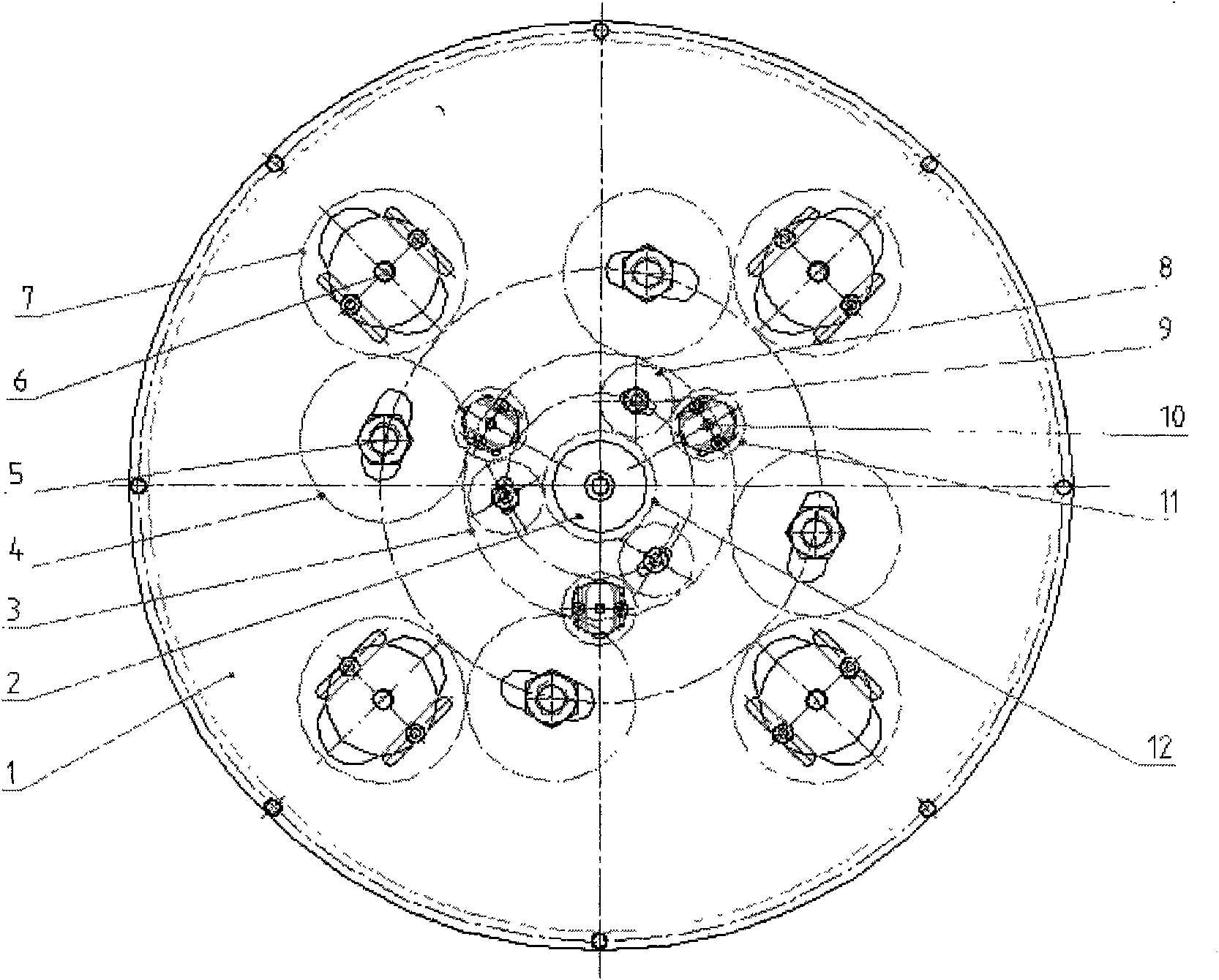
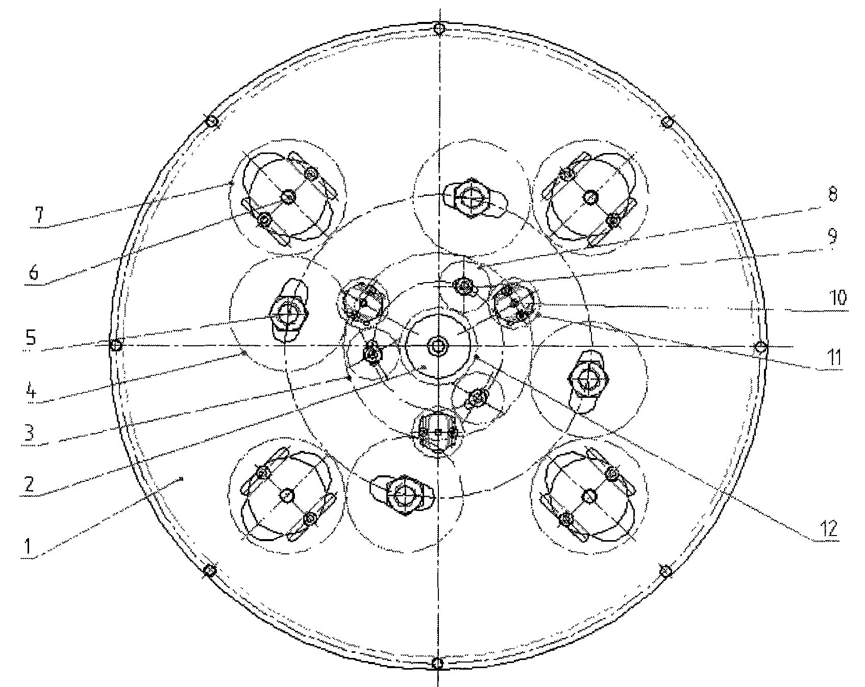
[0009] The present invention will be further described below in conjunction with accompanying drawing:

[0010] As shown in the accompanying drawings, a motor end cover drilling device is provided with a gearbox 1, a main gear shaft 2, a pinion gear shaft 6 and 10, a boundary wheel shaft 5 and 9, gears 3, 4, 7, 8, 11 and 12. It is characterized in that the device is powered by the movement of the main shaft of the ordinary lathe, that is, the main gear shaft 2 is put into the main shaft of the lathe, the drill bit sleeve is installed on the auxiliary gear shafts 6 and 10, and the gear on the big circle shaft 5 4 Mesh with the large gear 3 on the main gear shaft 2 and the gear 7 on the pinion shaft 6 at the same time, and the gear 8 on the small wheel shaft 9 simultaneously meshes with the pinion 12 on the main gear shaft 2 and the gear on the pinion shaft 10 11 meshing, the boundary wheel shafts 5, 9 and pinion shafts 6, 10 are made movable, as long as the position of the bou...


PUM


Abstract

The invention relates to a mounting hole-machining device for the end cover of a motor, comprising a gear box, a master gear shaft, an auxiliary gear shaft, a boundary wheel shaft, a gear, a bearing, a bearing cover and the like. The device is characterized in that the power of the device is supplied by the movement of the master shaft of a common machine lathe, namely the master gear shaft is arranged in the master shaft of the lathe, and a drill sleeve is arranged on the auxiliary gear shaft; the gear on the boundary wheel shaft is simultaneously engaged with the gears of the master shaft and the auxiliary gear shaft; the boundary wheel shaft and the auxiliary gear shaft are manufactured into be in a removable structure; the position of the auxiliary gear shaft can be adjusted by adjusting the position of the boundary wheel shaft so as to reach the process requirements of drilling the end covers with different models; and the essence is that the engagement of the gears is utilized to transmit torque so as to realize the purpose of drilling. The device has the advantages of simple structure, low cost and low failure rate.

Description

Technical field: [0001] The invention relates to a drilling mechanical equipment, in particular to a motor end cover drilling device. Background technique: [0002] At present, there are two main methods for processing the mounting holes of the motor end cover: one is to use a separate drilling die for each type of end cover to meet the drilling process requirements; the other is to purchase a special machine tool that can drill holes at one time. By adjusting the position of the drill bit, the technological requirements for drilling multiple types of end caps can be realized. Although the cost of the first method is low, the amount used when processing multiple models is too large. Although the second method solves the problem of processing multiple models, the cost is high and the operation is cumbersome. Invention content: [0003] The technical problem to be solved by the present invention is to overcome the deficiencies of the prior art and provide a machine tool tha...

Claims


Application Information

Patent Timeline
IPC IPC(8): B23B43/00B23B47/30
Inventor 张成李文洋
Owner 张成
Why Eureka
Try Eureka