
Hydraulic brake

A technology of hydraulic brakes and brake parts, which is applied to hydraulic drum brakes, brake types, axial upward brakes, etc., can solve the problems of low safety factor, heat generation, easy wear, etc. Effect

Inactive Publication Date: 2011-03-23
王世新
View PDF1 Cites 9 Cited by
  • Summary
  • Abstract
  • Description
  • Claims
  • Application Information

AI Technical Summary

Problems solved by technology

[0004] In order to overcome the seals of the existing hydraulic brakes, which are easy to wear and damage due to oil leakage, drum or belt hydraulic brakes need to manually adjust the braking gap; Insufficient energy, heat generation, damaged parts, polluted environment, and low safety factor

Method used


Image

  • Hydraulic brake
  • Hydraulic brake
  • Hydraulic brake

Examples


Embodiment Construction

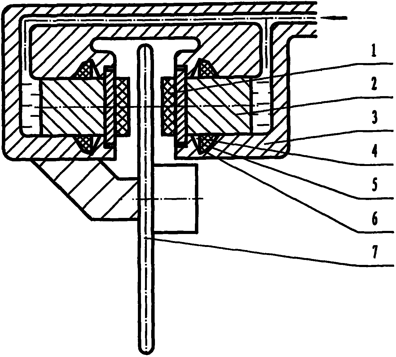
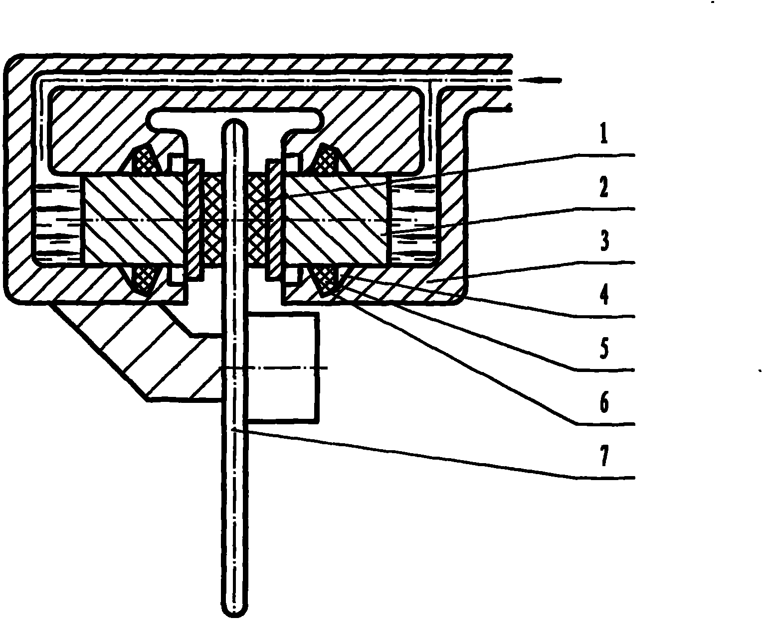
[0030] exist figure 1 Among them, the hydraulic brake is composed of a brake cylinder 3, a seal ring groove 6, a seal ring 5, a piston 2, a brake friction part 1, and a braked part 7, which are sequentially installed and connected, wherein the seal ring 5 is connected by the piston 2 and the seal ring The bottom of the groove 6 is extruded and sealed to be divided into an inner chamber and an outer chamber. Between the outer side of the sealing ring 5 and the wall of the sealing ring groove 6, a space 4 for the axial movement of the sealing ring 5 is provided. The axial movement space 4 is a coaxial circular ring, and the section is approximately trapezoidal or approximately "V"-shaped or rectangular, preferably "V"-shaped, such as figure 1 , Figure 6 , Figure 7 , Figure 9 , Figure 15 shown. The sealing ring 5 is a circular ring, installed in the sealing ring groove 6, squeezed by the piston 2 and the bottom of the sealing ring groove 6, and is basically statically se...


PUM


Abstract

The invention discloses a disk hydraulic brake capable of adjusting automobile brake clearance automatically. In the disk hydraulic brake, an annular space for a sealing ring to move axially is reserved in a sealing ring groove. The cross sections of the space, the sealing ring and the sealing ring groove are approximately trapezoid or V-shaped or triangular; and the sealing ring is pressed by the piston and the bottom of the sealing ring groove and performs static sealing basically. In braking, the piston and the inner ring of the sealing ring are driven by an oil pressure, the deformation resistance to axial movement of the inner ring of the sealing ring is overcome, a force for pulling back is stored, and a braking friction piece is linked to eliminate axial movement space and brake clearance and press a braked part at the same time, and thus, friction brake is realized. When braking is not needed, the oil pressure is withdrawn, and under the action of the pull-back force of the sealing ring, the machine parts and the two space clearances are restored. Thus, when braking is not needed, the machine parts are protected from friction, heating, damage oil leakage and long repair and replace period, and are energy-saving, emission-reducing, low in consumption and safe. The structure of the disk hydraulic brake is simple, and the production cost is unchanged basically.

Description

technical field [0001] The invention relates to a hydraulic brake capable of automatically adjusting the brake gap, in particular to a hydraulic brake capable of automatically adjusting and setting the return gap of the automobile disc brake. technical background [0002] At present, there are at least two kinds of known hydraulic brakes: one is an automobile disc hydraulic brake composed of a brake cylinder, a seal ring groove, a seal ring, a piston, a brake friction block, and a brake disc; A drum hydraulic brake composed of a brake cylinder, a leather cup or a sealing ring, a piston, a brake shoe, a return spring, and a brake drum. When braking, the braking force pressurizes the brake cylinder, and the piston of the disc hydraulic brake slides relative to the sealing ring and the inner wall of the oil cylinder, pushing the brake friction block to press the brake disc; or the cup or the drum hydraulic brake The sealing ring and the piston slide relative to the inner wall ...

Claims


Application Information

Patent Timeline
Patent Type & Authority Applications(China)
IPC IPC(8): F16D55/226F16D65/20F16D51/24F16D65/18
Inventor 王世新
Owner 王世新
Learn More