Electronic expansion valve structure

A technology of electronic expansion valve and valve body, applied in the direction of valve lift, valve details, valve device, etc., can solve the problems of unoptimized system, valve needle noise, long working stroke of valve needle, etc., achieve refrigeration system optimization and increase energy consumption than the effect

Inactive Publication Date: 2011-03-23
ZHEJIANG SANHUA CO LTD
View PDF7 Cites 6 Cited by
  • Summary
  • Abstract
  • Description
  • Claims
  • Application Information

AI Technical Summary

Problems solved by technology

[0003] However, in the refrigeration system, the valve needle in the valve structure of the electronic expansion valve moves in the valve seat hole to adjust the flow rate and open the valve. The valve needle is in a suspended state. Due to system pressure changes or refrigerant pulsation, it is easy to cause the valve needle to swing left and right. , when a certain swing range is reached, the valve needle will contact the hole wall of the valve seat to generate noise, especially in large-capacity commercial air-conditioning systems, due to the high operating pressure of the system, this problem is more prominent; at the same time, the commercial expansion valve Due to the large throttling change, the valve needle is required to have a long working stroke. However, in the prior art, a combi

Method used


Image

  • Electronic expansion valve structure
  • Electronic expansion valve structure
  • Electronic expansion valve structure

Examples


Embodiment Construction

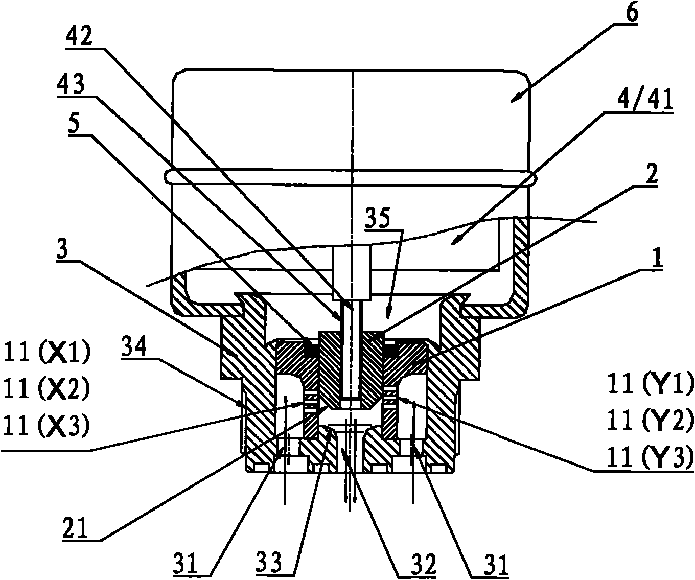
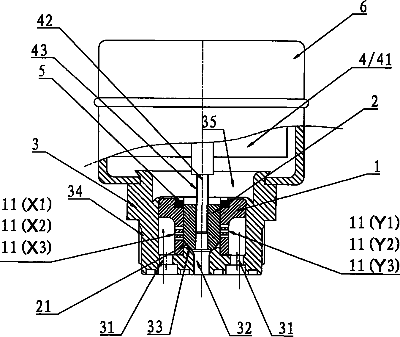
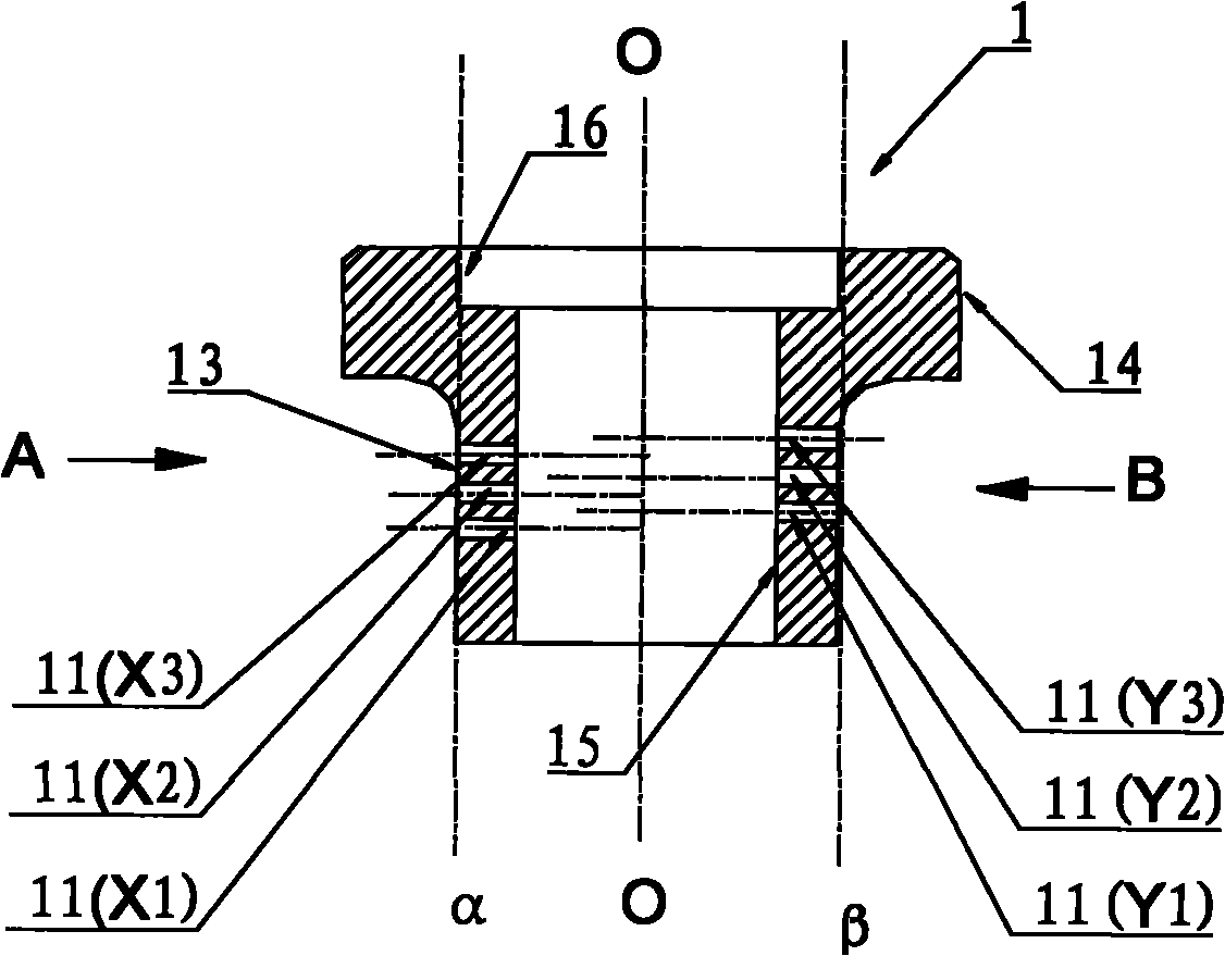
[0056] Figure 1A It is a schematic structural diagram of one of the specific embodiments provided by the present invention under the throttling working state; Figure 1B It is a schematic structural diagram of the specific embodiment in a closed state; image 3 It is a front view and a side view of the anti-rotation gasket structure in the above embodiment; Figure 4It is the front view and top view of the spool structure.

[0057] Such as Figure 1A and Figure 1B shown. The structure of the electronic expansion valve includes a cover body 6 riveted and fixed to the valve body 3 and a drive motor 41 (a stepper motor in this embodiment) fixed in the cover body 6. The front end of the motor 41 is connected with a transmission shaft 42 to drive The motor 41 and the drive shaft 42 together form the drive device 4 . The detection control module of the refrigeration system (such as air conditioner) converts the detected parameters such as the pressure / temperature change of t...


PUM


Abstract

The invention relates to an electronic expansion valve structure, belonging to the technical field of refrigeration control. In the prior art, the pressure and pulsation of fluid cause unstable work, and the node flow related parameters of specific multi-point positions are difficult to set accurately in the prior art. The electronic expansion valve structure comprises a drive device controlled via sensing signals, a valve body provided with an inlet channel and an outlet channel, a throttle sleeve body fixed on the valve body and provided with throttling ports, and a valve core, wherein the valve core slides relative to the throttle sleeve body under the drive of the drive device to change the size of the throttle ports or to open/close the throttle ports. The electronic expansion valve structure is characterized in that the throttle ports are a plurality of circumferential open pores arranged on the throttle sleeve body. The invention avoids the problem that the work reliability is reduced due to the pressure and the pulsation of the fluid in the process of the throttling process; meanwhile, by regulating the positions and the quantity of the open pores and setting the node flow related parameters of multiple key points, the refrigerating system is optimized and the energy consumption ratio is improved.

Description

technical field [0001] The invention relates to an electronic expansion valve structure, which is a device for controlling the throttle flow by adjusting the size of the throttle port, belongs to the technical field of refrigeration control, is suitable for vapor compression heat pump systems, etc., and is especially suitable for use in commercial large-capacity air-conditioning systems electronic expansion valve. Background technique [0002] As a throttling device, the electronic expansion valve is widely used in the circuit of the refrigeration system. The function of the electronic expansion valve is to adjust the cooling capacity flowing into the evaporator, supply the optimum amount of refrigerant to the evaporator, and ensure the stable operation of the refrigeration system. The typical structure of the electronic expansion valve in the prior art is as follows: Figure 10 As shown, it includes a valve structure 901 , a transmission part 902 , a motor 903 , an inlet co...

Claims


Application Information

Patent Timeline
IPC IPC(8): F16K1/00F16K1/32F16K31/04F16K31/64F16K47/04
Inventor 王庆勇
Owner ZHEJIANG SANHUA CO LTD
Why Eureka
Try Eureka