
Light guide plate

A technology of light guide plate and light guide structure, applied in the field of light guide plate, can solve the problems of bright lines in bright and dark areas, and the effect is not very ideal, etc.

Inactive Publication Date: 2011-03-23
AU OPTRONICS CORP
View PDF0 Cites 9 Cited by
  • Summary
  • Abstract
  • Description
  • Claims
  • Application Information

AI Technical Summary

Problems solved by technology

However, due to the small size of the light-emitting diode, its light is too concentrated, so the light emitted by the light-emitting diode is too concentrated after it enters the light guide plate. Although it is scattered by the light guide plate, it is still easy to produce problems such as bright and dark areas or bright lines.
[0003] Although there are designs in the prior art to form various light incident structures on the light incident surface of the light guide plate to increase the uniformity of the outgoing light, the effects are not very satisfactory.

Method used


Image

  • Light guide plate
  • Light guide plate
  • Light guide plate

Examples


no. 1 example

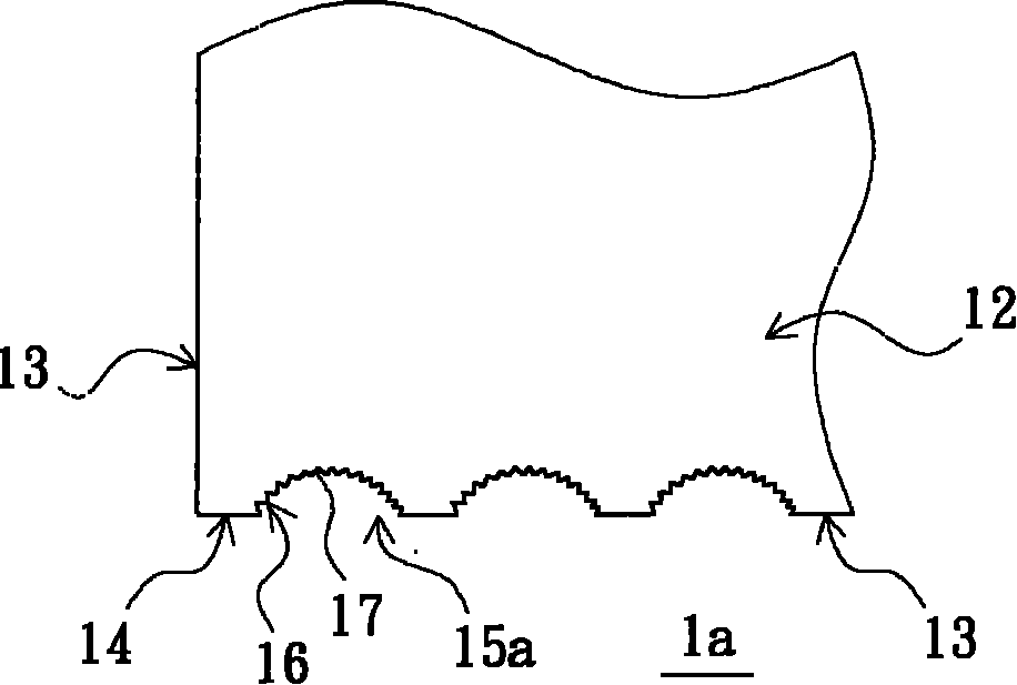
[0036] figure 2 It is a schematic top view of the light guide plate provided by the second embodiment of the present invention. see figure 2 , the light guide plate 1 a of this embodiment is similar to the light guide plate 1 of the first embodiment, the difference lies in that the arc columnar structure 15 a of the light guide plate 1 a is an arc columnar depression recessed in the light incident surface 14 . Compared with the first embodiment, since the arc columnar structure 15a of this embodiment is an arc columnar depression recessed in the light incident surface 14, the incident rate of the light source is higher and has a better effect of diverging light, so The uniformity of the surface light source emitted from the light emitting surface 12 can be further improved.

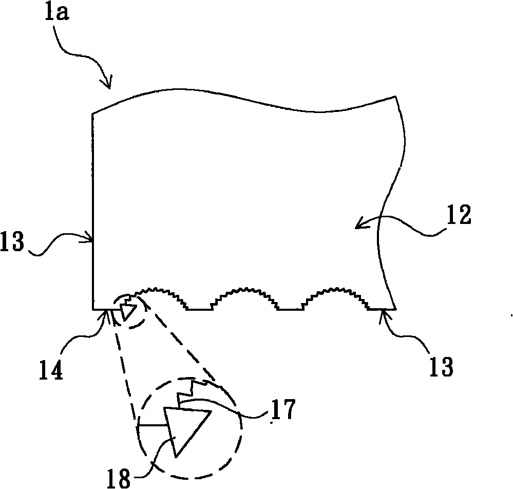
[0037] image 3 yes figure 2 A schematic diagram of the fabrication method of the light guide plate. see image 3 The above-mentioned plurality of V-shaped grooves 17 can be formed by cutting one...


PUM


Abstract

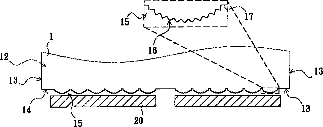
The invention relates to a light guide plate comprising a incident surface, wherein the incident surface is provided with at least one circular arc-shaped structure and a plurality of V-shaped grooves along the circular arc-shaped surface of the circular arc-shaped structure; the V-shaped grooves in the light guide plate are formed by cutting through the rotating around the central shaft by utilizing a cutter; the processing technology is simple and rapid; the shape of the produced grooves has good repeatability; and the grooves in the circular arc-shaped structure make the light rays emitted by a light emitting diode be effectively scattered when entering the light guide plate so as to eliminate the bright and dark areas of the light emitting from the light guide plate and the phenomena of uneven light emitting of horoscopic bright rays and the like.

Description

technical field [0001] The invention relates to a light guide plate, in particular to a light guide plate with an improved light incident structure. Background technique [0002] Today, liquid crystal displays have been widely used in various electronic devices that require display. However, since the liquid crystal material itself does not have self-luminous properties, it is necessary to use a special backlight module to provide the liquid crystal display panel with a backlight for displaying images. A backlight module generally includes a light source, such as a cold cathode fluorescent lamp or a light emitting diode, and a light guide plate for scattering the light emitted by the light source to provide uniform surface-emitted light. In recent years, compared with traditional CCFLs, LED technology has the advantages of environmental protection, energy saving, and longer life, so it is more and more widely used in backlight modules. However, due to the small size of the...

Claims


Application Information

Patent Timeline
Patent Type & Authority Applications(China)
IPC IPC(8): F21V8/00G02F1/13357F21Y101/02
Inventor 张泰豪许笠晨廖声荣
Owner AU OPTRONICS CORP
Learn More