
Yarn splicing device and textile machine equipped with the same

A joint device and equipment technology, which is applied in the field of fiber machinery, can solve the problems of difficult fluid flow setting, setting error, and difficulty in immediately changing the flow adjustment mechanism, etc., and achieves the effect of high reproducibility and suppression of fluid turbulence

Inactive Publication Date: 2011-03-30
MURATA MASCH LTD
View PDF7 Cites 11 Cited by
  • Summary
  • Abstract
  • Description
  • Claims
  • Application Information

AI Technical Summary

Problems solved by technology

Although the above-mentioned existing flow adjustment mechanism can change the setting steplessly, it is set by the amount of rotation of the screw or the height of the screw protrusion.
Therefore, there is a problem that an error is included in the setting every time the setting of the flow rate adjustment mechanism is changed.
In addition, since the setting is made from the outside of the fluid flow path, it is not possible to directly confirm how much the fluid flow path is actually opened.
Therefore, it is difficult for the above-mentioned existing piecing device to reproduce the setting of the flow rate adjustment mechanism to the most appropriate setting corresponding to the characteristics of the yarn, so it is difficult to set the fluid flow rate to an appropriate value corresponding to the characteristics of the yarn. flow
[0006] In addition, in the above-mentioned conventional joint device, it takes time to adjust the amount of rotation of the screw or the height of the protrusion, so it is difficult to immediately change the setting of the flow rate adjustment mechanism.

Method used


Image

  • Yarn splicing device and textile machine equipped with the same
  • Yarn splicing device and textile machine equipped with the same
  • Yarn splicing device and textile machine equipped with the same

Examples


Embodiment Construction

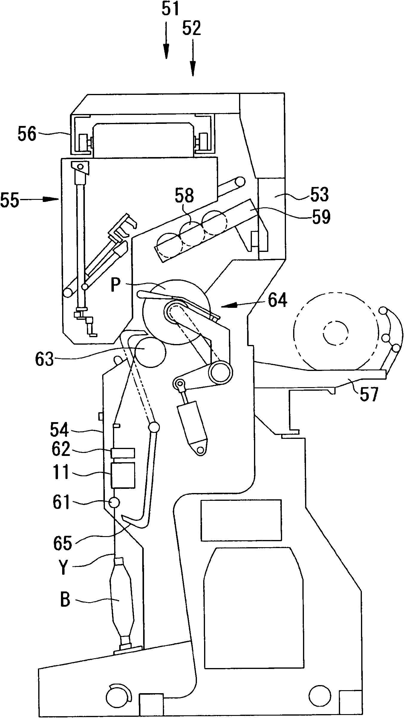
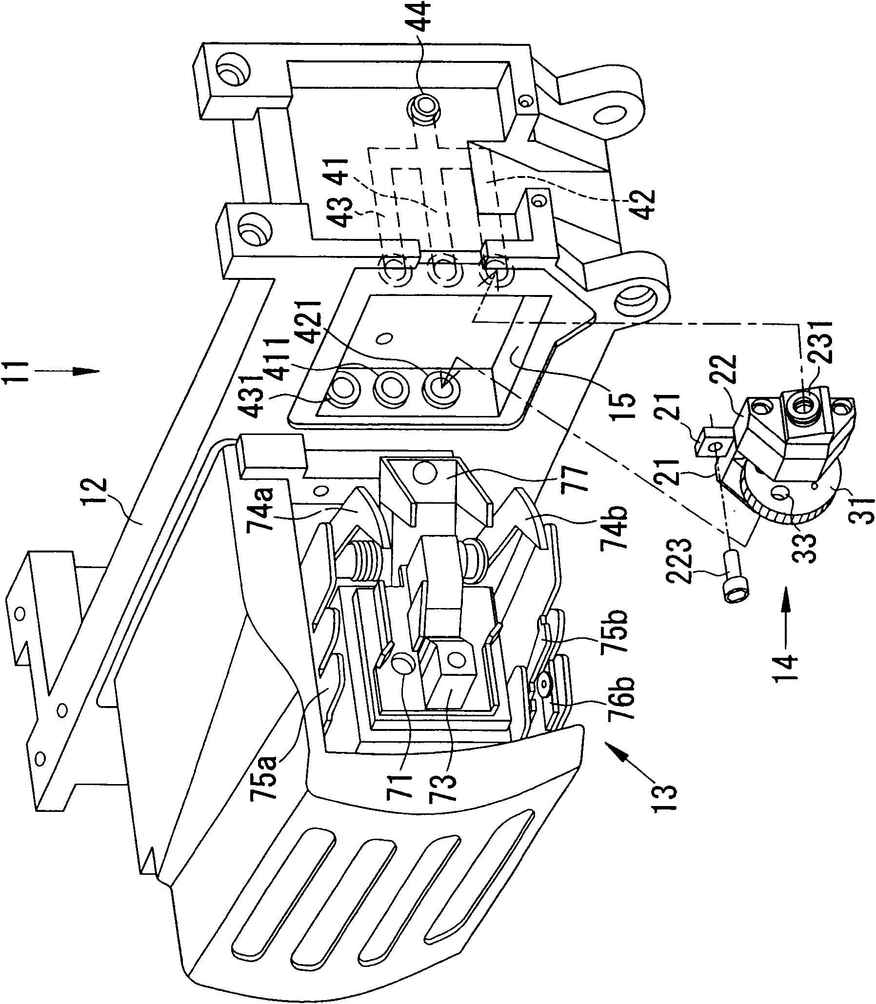
[0034] figure 1 A sectional view showing a winder 51 as a textile machine using the yarn joining device 11 according to the first embodiment of the present invention. The winder 51 has a plurality of yarn winders 52 arranged side by side in one direction, and the yarn winders 52 in the winder 51 rewind the yarn Y of the yarn supplying bobbin B to form a package P. In addition, although the case where the yarn joining device 11 of the present invention is used in the winder 51 will be described below, the yarn joining device 11 of the present invention can also be used to convert a fiber bundle into a spun yarn and wind it up to form a package. P spinning machinery.

[0035] Such as figure 1 As shown, the main frame 53 is arranged along the direction in which the yarn winding machines 52 are arranged side by side. The main frame 53 supports a unit frame 54 for supporting devices constituting the yarn winding machine 52 and a rail 56 for running the doffing device 55 in the d...


PUM


Abstract

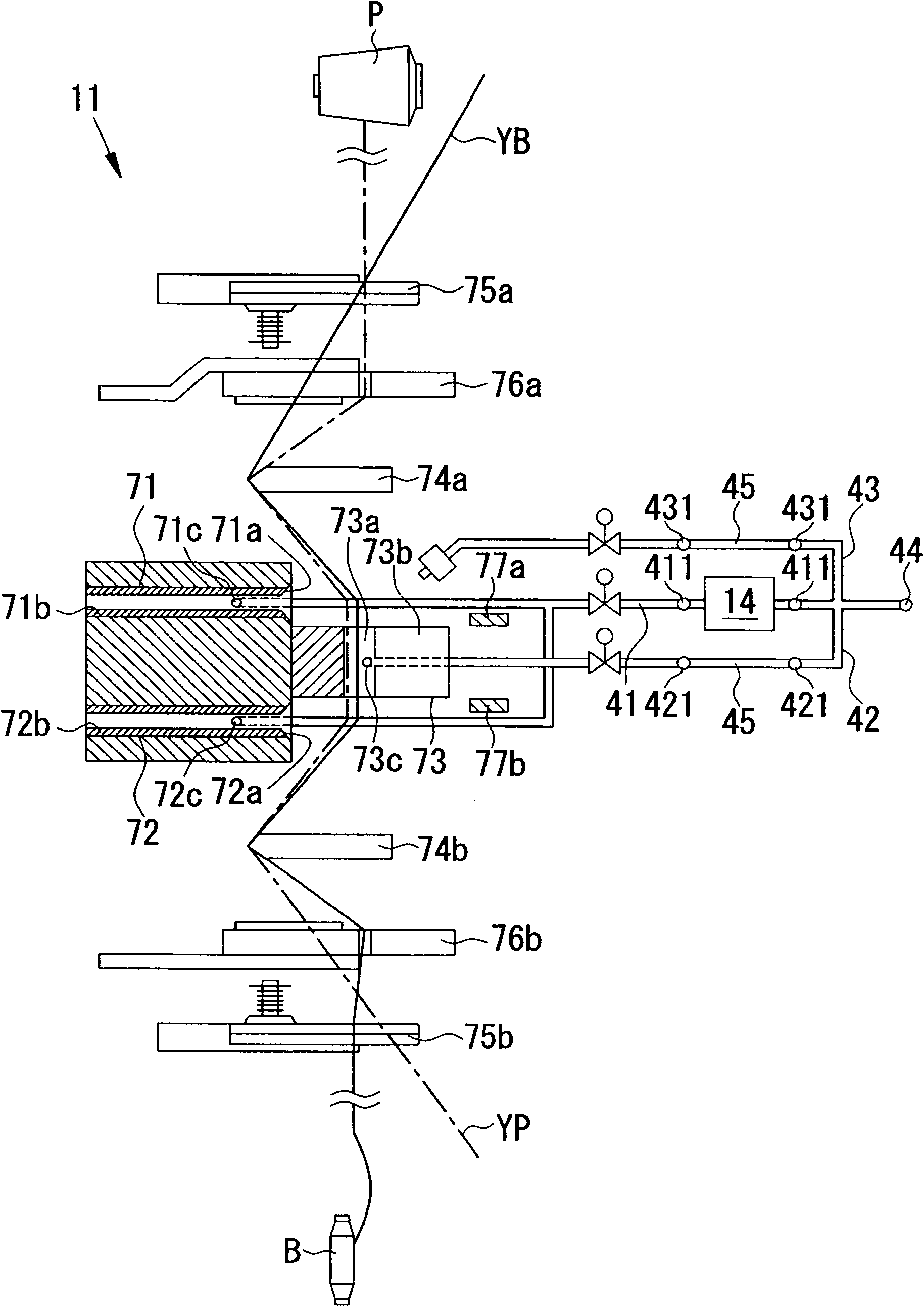
A fluid type yarn splicing device for performing yarn splicing includes a flow rate adjustment mechanism for adjusting a flow rate of a fluid, wherein the flow rate adjustment mechanism includes a narrowing member for narrowing an opening area of a flow path of the fluid, the narrowing member being configured such that an opening area of the flow path that differs in a step-wise manner is selectable, and the flow rate of the fluid being selected in a step-wise manner by switching the selection of the opening area.

Description

technical field [0001] The present invention relates to a fluid type piecing device for performing piecing, and a textile machine equipped with the same. Background technique [0002] Conventionally, we know a winder that rewinds a yarn to form a package, or a spinning machine that converts a fiber bundle into a spun yarn and then winds it into a package. These textile machines are provided with a piecing device for piecing the yarn end on the package side and the yarn end on the yarn feeding side when the yarn is broken or the yarn is cut by the yarn defect detection device. [0003] As a piecing device, there is known a fluid type piecing device that uses a fluid (for example, compressed air) to untwist two yarn ends that require piecing and to connect the two untwisted yarn ends. The piecing device described in Japanese Patent Application Laid-Open No. 59-211632 includes an untwisting nozzle for untwisting two yarn ends, and a piecing nozzle for connecting two untwisted ...

Claims


Application Information

Patent Timeline
Patent Type & Authority Applications(China)
IPC IPC(8): B65H69/06
CPCB65H2701/31B65H69/063
Inventor 泽田映梅冈利成
Owner MURATA MASCH LTD
Learn More