Compressor
A technology of compressors and elements, applied in the field of compressors, can solve problems such as insufficiency, and achieve the effects of reducing contact area, suppressing deformation, and suppressing transmission vibration
- Summary
- Abstract
- Description
- Claims
- Application Information
AI Technical Summary
Problems solved by technology
Method used
Image
Examples
Embodiment 1
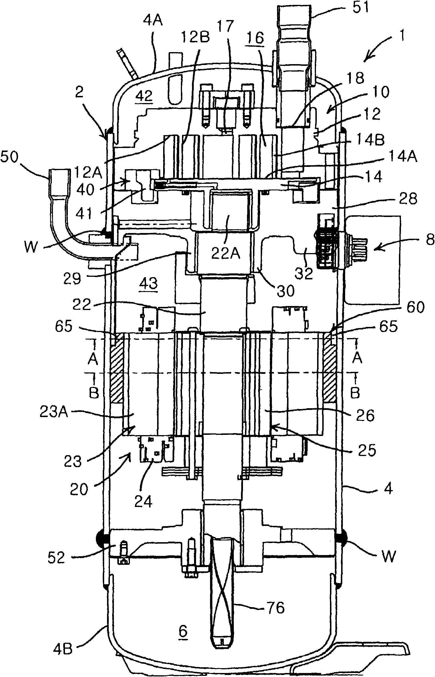
[0060] figure 1 It is a vertical side view of a compressor to which an embodiment of the present invention is applied. The compressor 1 is an internal high-pressure type scroll compressor, and constitutes a known refrigerant circuit connected to a condenser, a decompression device, and an evaporator not shown. The scroll compressor 1 includes: a vertical cylindrical airtight container 2 made of steel plates; a scroll compression element 10 driven by a rotating shaft 22 that is accommodated in the upper part of the inner space of the airtight container 2; Electric element 20 below element 10.
[0061]Airtight container 2 comprises: container main body 4, and its bottom is oil storage part 6, and accommodates electric element 20 (electric motor) and scroll compression element 10; The mode installation of roughly bowl-shaped bottom 4B, it is installed with the mode of closing the bottom opening of this container main body 4. Moreover, a circular mounting hole not shown is form...
Embodiment 2
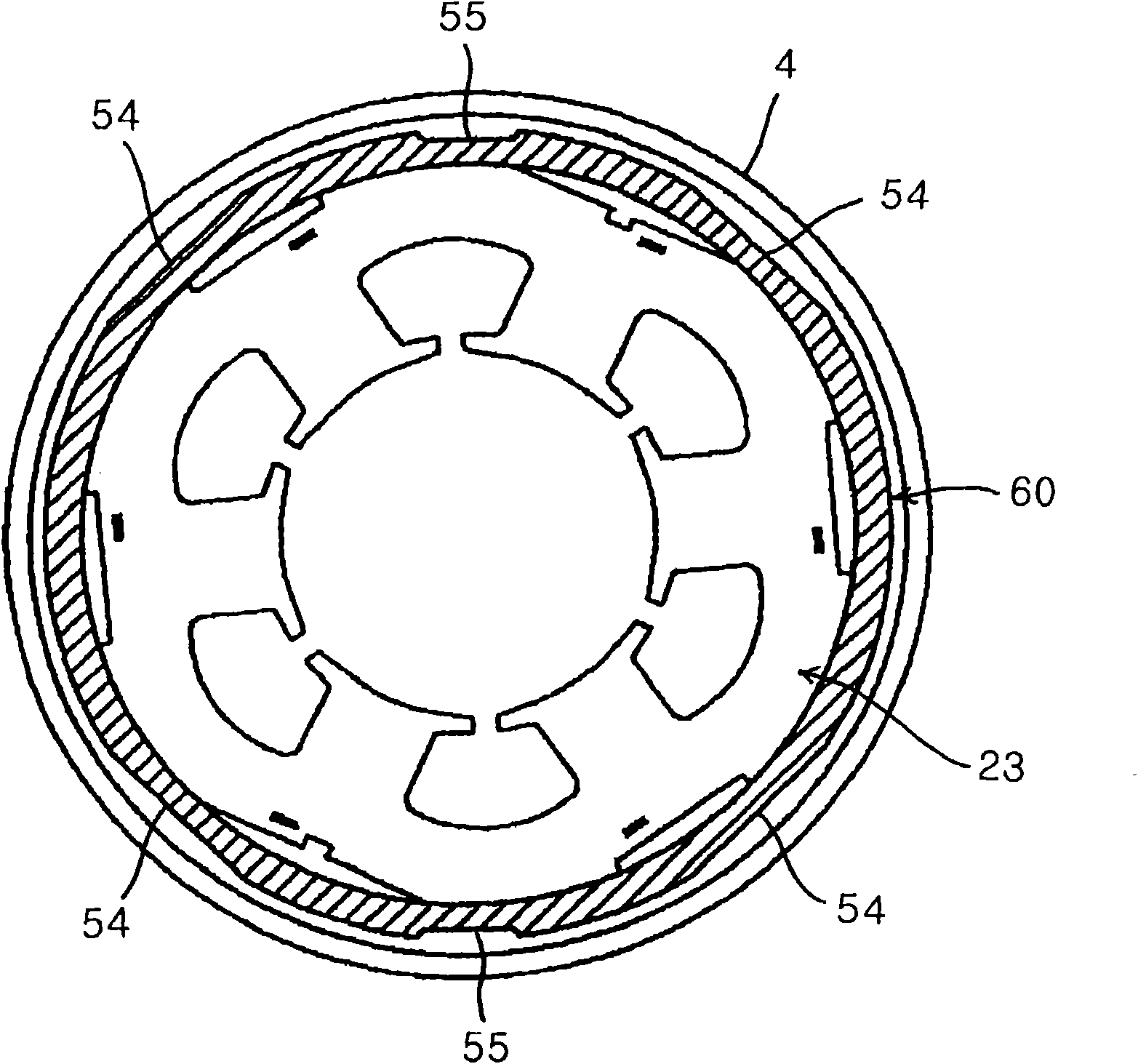
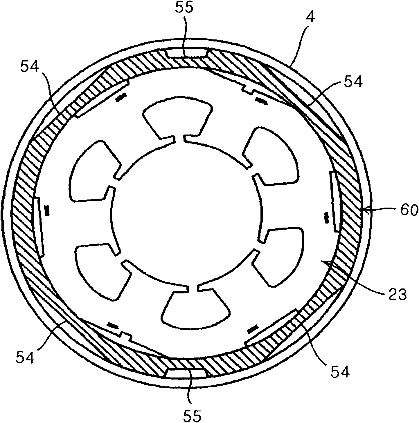
[0091] In addition, in the above-mentioned first embodiment, by providing the notch 65 around the upper portion of the spacer 60 on the airtight container 2 side, the area of the spacer 60 in contact with the container body 4 of the airtight container 2 is formed to be larger than the area of the spacer 60 in contact with the stator 23 . area is small, but the invention is not limited thereto, for example, as Figure 5 As shown, the area of the spacer 70 in contact with the container body 4 of the airtight container 2 may be formed smaller than the area of the spacer 70 in contact with the stator 23 by providing a cutout 75 around the lower portion of the surface of the spacer 70 on the airtight container 2 side. .
[0092] Figure 5 The shown cutout 75 is formed over the entire circumference on the surface (outer peripheral surface) of the spacer 70 on the airtight container 2 side, similarly to the cutout 65 in the first embodiment. The slit 65 of the first embodim...
Embodiment 3
[0098] Figure 6 It is a vertical side view of a scroll compressor to which another embodiment of the present invention is applied. exist Figure 6 , marked with the above Figure 1 to Figure 5 Components with the same symbols have the same or similar effects or functions, and descriptions are omitted here. Figure 6 Shown at 80 is the spacer of this embodiment. The dimension of the spacer 80 in the axial direction of the rotating shaft 22 is formed to be the same as the dimension of the stator 23 in the axial direction of the rotating shaft 22 . That is, the upper end of the stator 23 is substantially on the same plane as the upper end of the spacer 80 , and the lower end of the stator 23 is substantially on the same plane as the lower end of the spacer 80 .
[0099] In addition, similarly to the above-described respective embodiments, the inner peripheral surface (the surface on the stator 23 side) of the spacer 80 is not provided with notches, unevenness, and the like a...
PUM
 Abstract
Description
Claims
Application Information
 - R&D
- Intellectual Property
- Life Sciences
- Materials
- Tech Scout
- Unparalleled Data Quality
- Higher Quality Content
- 60% Fewer Hallucinations
Browse by: Latest US Patents, China's latest patents, Technical Efficacy Thesaurus, Application Domain, Technology Topic, Popular Technical Reports.
© 2025 PatSnap. All rights reserved.Legal|Privacy policy|Modern Slavery Act Transparency Statement|Sitemap|About US| Contact US: help@patsnap.com


