
Automatic test system and method of programmable logic device on basis of boundary scan

An automatic test system and boundary scan technology, applied in the field of electronics, can solve problems such as non-compliance with rapid testing, complex supporting software, and high learning costs

Inactive Publication Date: 2011-03-30
FUDAN UNIV
View PDF3 Cites 49 Cited by
  • Summary
  • Abstract
  • Description
  • Claims
  • Application Information

AI Technical Summary

Problems solved by technology

This method has high versatility and high accuracy, but the corresponding supporting software is relatively complicated, the learning cost is high, and the supporting hardware is extremely expensive, which does not meet the requirements of rapid testing at a lower cost

Method used

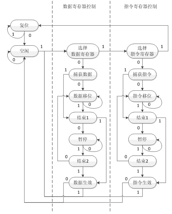
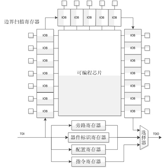
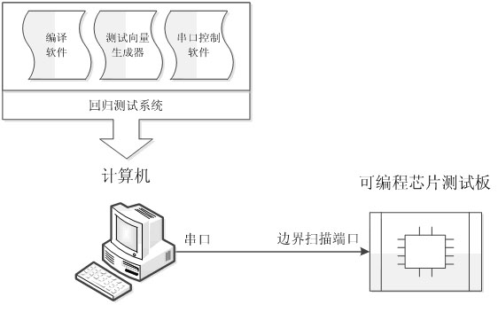

Image

  • Automatic test system and method of programmable logic device on basis of boundary scan
  • Automatic test system and method of programmable logic device on basis of boundary scan
  • Automatic test system and method of programmable logic device on basis of boundary scan

Examples


Embodiment Construction

[0045] In order to simulate the test needs of users, we selected a total of 105 examples to be tested, including 51 examples of pure combinational circuits and 56 examples of sequential circuits; from the functional point of view, they include simple adders, multipliers, comparison device, encryption and decryption logic, as well as complex singing, VGA port control, communication and other applications. In addition, an FPGA chip selected by the test board supports JTAG boundary-scan technology, and has matching compiling software to meet the test requirements.

[0046] When testing, you only need to enter a command in the command line environment, and all 105 examples can be synthesized, compiled, downloaded, tested and counted. The whole process does not require manual operation, which greatly facilitates users to carry out repeated tests. It has been verified that most of the examples can pass the test at one time, and the examples that fail the test can be found by checkin...


PUM


Abstract

The invention belongs to the field of electronic technology, in particular to an automatic test system and method of a programmable logic device on the basis of boundary scan. The test method comprises the following steps: generating a chip configuration file; downloading and configuring an FPGA (field programmable gate array) chip; generating and loading a test vector; comparing test results; building a corresponding test system; and completely realizing automation. In the invention, the test vector of an item to be tested is automatically generated by a user through software, and the on-line test of the hardware function of a user circuit is realized by combining JTAG (joint test action group) automatic downloading test software. Scripted test environment converts a series of complex manual test operation into full automatic software flow so as to greatly improve test speed and accuracy.

Description

technical field [0001] The invention belongs to the field of electronic technology, and in particular relates to an automatic testing method of a programmable device. Background technique [0002] Field Programmable Gate Array (Field Programmable Gate Array, FPGA), which is in Programmable Array Logic (Programmable Array Logic, PAL), General Array Logic (Generic Array Logic, GAL), Complex Programmable Logic Device (Complex Programmable Logic Device , CPLD) and other programmable devices based on the further development of the product. It first appeared as a way to verify the prototype function of an application specific integrated circuit (ASIC), which not only solved the shortcomings of custom circuits, but also overcome the shortcomings of the limited number of original programmable device gates. [0003] Due to the short design cycle of FPGA, fast time to market, low Non-Recursive Engineering (NRE), and dynamic reconfigurability, it is widely used in civil communications...

Claims


Application Information

Patent Timeline
Patent Type & Authority Applications(China)
IPC IPC(8): G01R31/317G01R31/3183
Inventor 王伶俐王颖周学功童家榕包杰
Owner FUDAN UNIV
Learn More