Metal microstructure forming method

A metal microstructure and metal structure technology, applied in optics, optomechanical equipment, instruments, etc., can solve the problems affecting the reliability of microstructure components, substrate deformation, and adhesion reduction.

Inactive Publication Date: 2011-03-30
PREMTEK INT
View PDF4 Cites 9 Cited by
  • Summary
  • Abstract
  • Description
  • Claims
  • Application Information

AI Technical Summary

Problems solved by technology

[0009] Yet the shortcoming of the U.S. patent of above-mentioned US 5,190,637 is: 1. Need electroplating second kind of metal again, if the area occupied by second kind of metal is quite large, must reduce the residual stress that electroplating causes as far as possible, otherwise easily make adhesion The substrate of the main metal is deformed, making it impossible to carry out the subsequent manufacturing process; 2. There is residual stress between each layer of the main metal; and, 3. Although the etching solution is adjusted as much as possible to have a higher selectivity ratio between the main metal and the second metal , but the etchant will still seep into the interface of each layer, resulting in a decrease in the adhesion of each layer, which in turn affects the reliability of the microstructure components

Method used


Image

  • Metal microstructure forming method
  • Metal microstructure forming method
  • Metal microstructure forming method

Examples


Embodiment Construction

[0027] The implementation of the present invention will be described in more detail below in conjunction with the accompanying drawings, so that those skilled in the art can implement it after studying this specification.

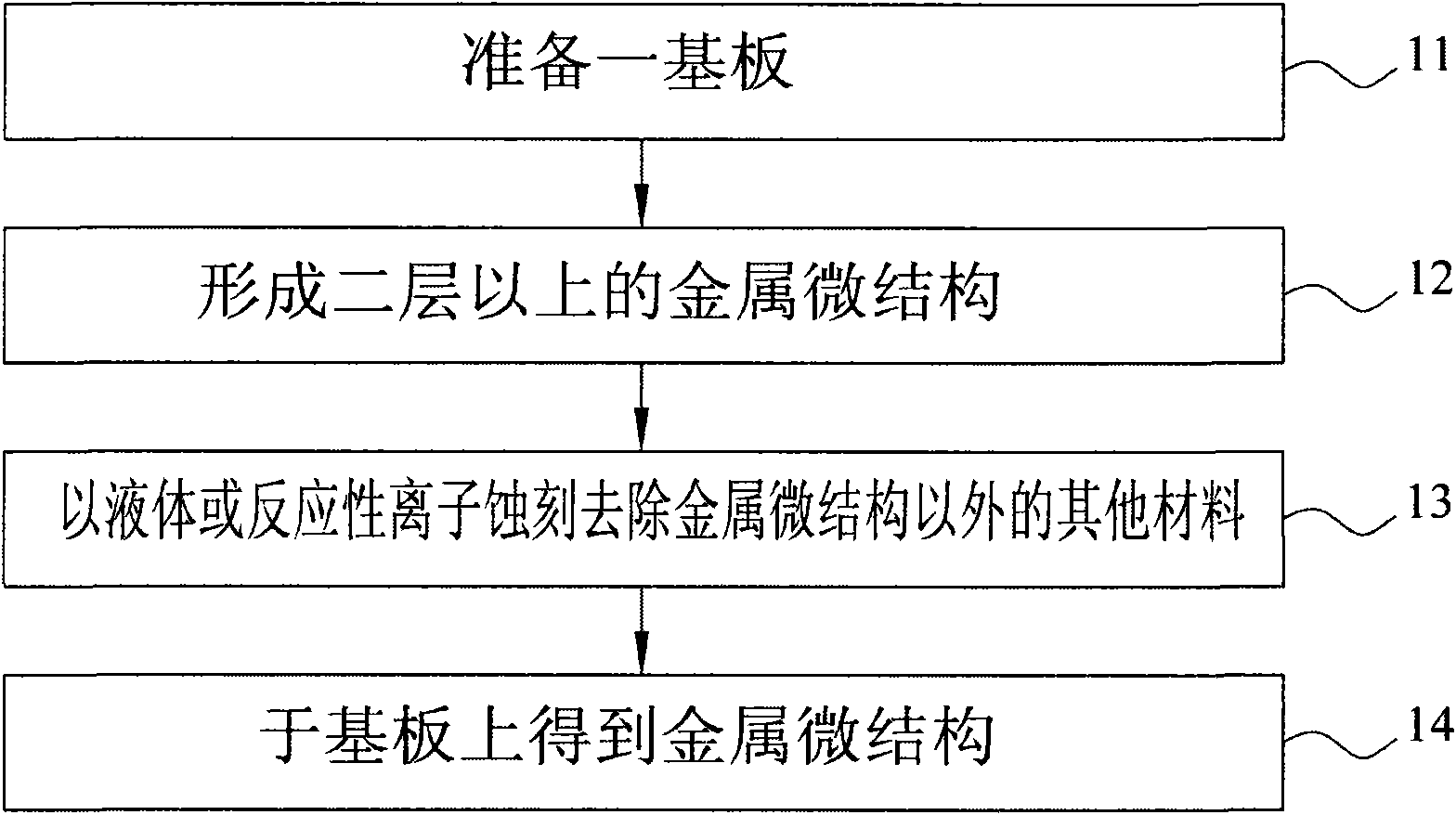
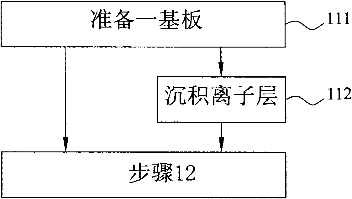
[0028] figure 1 It is a flowchart for illustrating the process steps of the metal microstructure forming method of the present invention. Such as figure 1 Shown in is the metal microstructure forming method of the present invention. Firstly, in step 11 , a substrate is prepared for subsequent metal microstructure formation on the substrate, and the process proceeds to step 12 .

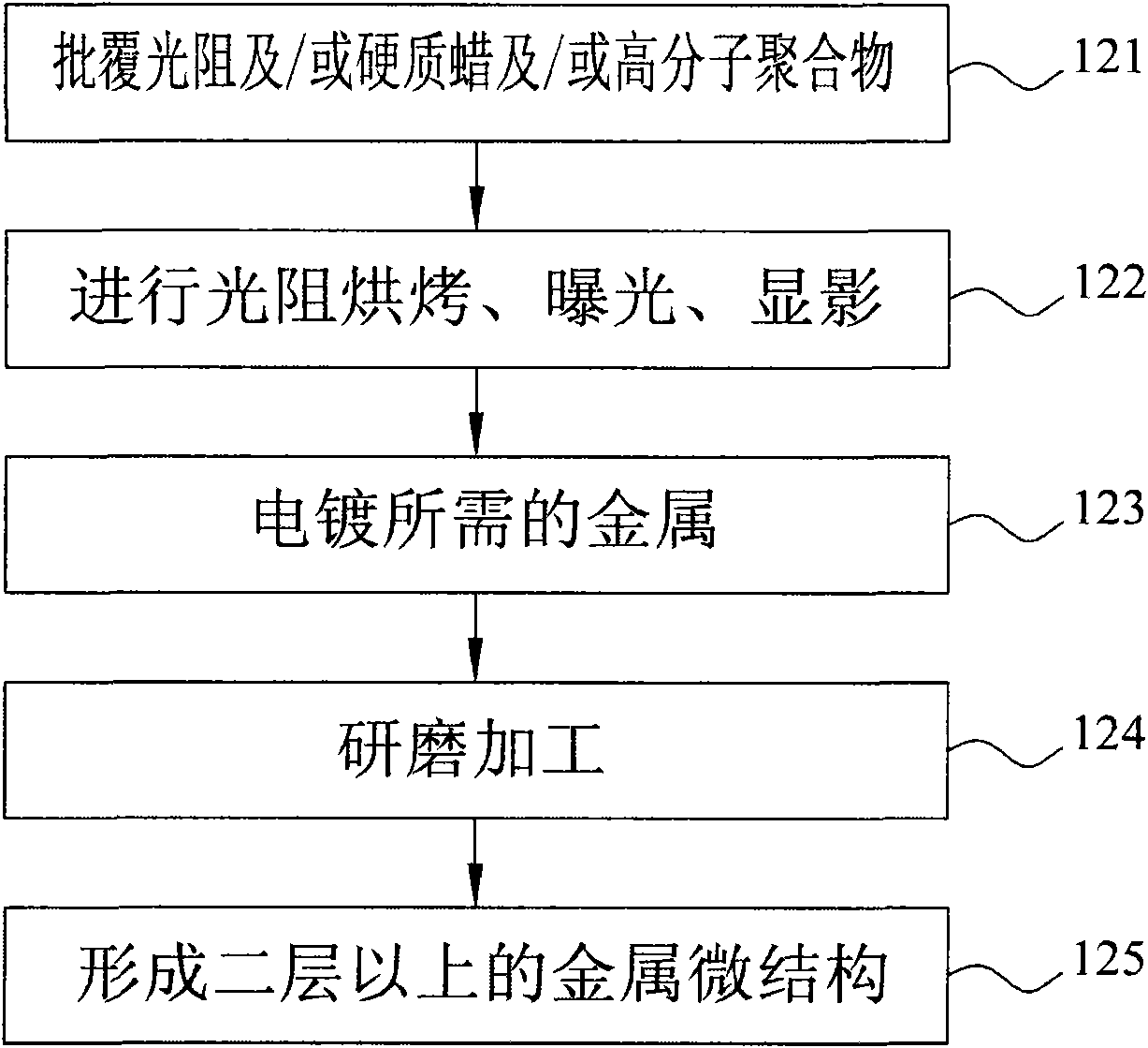
[0029] In step 12, two or more layers of metal microstructures are successively formed on the surface of the substrate, where each layer of metal microstructures is composed of a material, and the two or more layers of metal microstructures can be made of the same material and / or consist of different materials, and go to step 13.

[0030] In step 13, liquid or reactive ion etch...


PUM


Abstract

The invention discloses a metal microstructure forming method which is applied to the manufacturing process of a microstructure component; by utilizing the metal microstructure forming method, a second type of metal is not needed to be electric-plated to surround the periphery of the metal and the second type of metal is not needed to be etched when a three-dimensional metal microstructure of the microstructure component is formed, therefore, the residual stress caused by electric-plating is reduced, no residual stress exists among the metal layers, a base plate attached by the metal is not deformed and the implementing of the follow-up manufacturing process of the microstructure component is not affected; in addition, as the second type of metal is not needed to be etched, the problem that etchants are permeated to the interface at each layer does not exist, adhesive force reduction at each layer can not caused, so as not to affect the functions of the microstructure component.

Description

technical field [0001] The invention relates to a method for forming a microstructure, in particular to a method for forming a metal microstructure, which is applied to the manufacturing process of microstructure components, can reduce the residual stress caused by electroplating, there will be no residual stress between metal layers, and the metal attached The substrate will not be deformed and will not affect the subsequent manufacturing process of the microstructure component. Background technique [0002] For the current MEMS technology, although MEMS has the advantages of miniaturization, batch production, and can provide many high-performance components, the goal it pursues is still how to manufacture smaller, energy-efficient A MEMS with lower loss, more powerful functions and more stable system. [0003] However, in order to achieve a more stable and reliable MEMS system, the microcomponents on it usually have to have a good three-dimensional metal microstructure, s...

Claims


Application Information

Patent Timeline
Patent Type & Authority Applications(China)
IPC IPC(8): G03F7/00C25D5/02
Inventor 王宏杰黄雅如
Owner PREMTEK INT
Why Eureka
Try Eureka