Supercharge Your Innovation With Domain-Expert AI Agents!

Path track point calculating device and method for numerical control system

A numerical control and calculation method technology, which is applied in general control systems, control/regulation systems, program control, etc., can solve problems such as the inability to guarantee the continuity of higher-order curves and reduce practicability

Active Publication Date: 2011-03-30
DELTA ELECTRONICS INC
View PDF1 Cites 1 Cited by
  • Summary
  • Abstract
  • Description
  • Claims
  • Application Information

AI Technical Summary

Problems solved by technology

However, although it increases the complexity of the design of the command return calculator, it also reduces the practicability of this method, making this method unable to guarantee the continuity of higher-order curves

Method used


Image

  • Path track point calculating device and method for numerical control system
  • Path track point calculating device and method for numerical control system
  • Path track point calculating device and method for numerical control system

Examples


Embodiment Construction

[0030] Below in conjunction with accompanying drawing, structural principle and working principle of the present invention are specifically described:

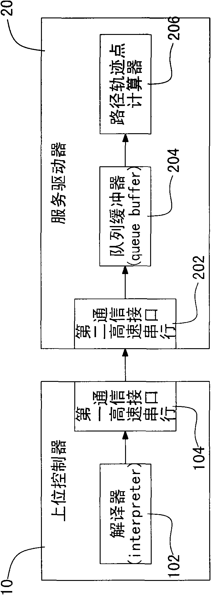
[0031] See figure 1 , is a schematic diagram of communication between a host controller and a service driver of the path track point calculation device of the numerical control system of the present invention. The path track point calculation device of the numerical control system is applied to the calculation of the machining path track points of a computer numerical control machine tool, and a G-code file generated by computer-aided manufacturing (CAM) software is used to define the machining path track. The path track point calculation device mainly includes a host controller 10 and a service driver 20 . The host controller 10 includes an interpreter 102 and a first high-speed serial communication interface 104 . In addition, the service driver 20 includes a second high-speed serial communication interface 202 , a queue b...


PUM


Abstract

The invention discloses a path track point calculating device and a path track point calculating method for a numerical control system, which are applied to processing path track point calculation for a computer numerical control tool machine. The path track point calculating device mainly comprises an upper controller and a service driver, wherein the upper controller provides an interpreter for interpreting the processing path track so as to generate a plurality of executive instructions, wherein the executive instructions are transmitted to a queue buffer of the service driver for storage by the upper controller through a serial communication interface; and a path track point calculator receives and calculates the executive instructions transmitted by the queue buffer so as to generate a plurality of path track points.

Description

technical field [0001] The present invention relates to a path track point calculation device and calculation method of a numerical control system, in particular to a path track point calculation device and calculation method of a numerical control system with a queue buffer. Background technique [0002] Motion control is the key core technology in precision machining machinery. Its application scope covers industrial machinery with positioning control or speed control to various types of high-precision CNC machine tools. The establishment of a motion control system must integrate various software and hardware technologies. For users, in addition to the basic functional requirements of the system, the cost, system stability, frequency of use, warranty service, and other software and hardware Scalability and compatibility... etc. are also factors for evaluating motion control systems. In addition, in consideration of the actual motion control system, not only the position o...

Claims


Application Information

Patent Timeline
IPC IPC(8): G05B19/4097
Inventor 蔡清雄
Owner DELTA ELECTRONICS INC
Features
  • R&D
  • Intellectual Property
  • Life Sciences
  • Materials
  • Tech Scout
  • Unparalleled Data Quality
  • Higher Quality Content
  • 60% Fewer Hallucinations
Learn More