Audio signal separating device and operation method thereof

A technology of audio signal and separation device, applied in voice analysis, transducer circuit, instrument, etc., can solve problems such as spatial aliasing, and achieve the effect of improving signal-to-noise ratio

Inactive Publication Date: 2011-03-30
SPRING FOUND OF NCTU
0 Cites 11 Cited by

AI-Extracted Technical Summary

Problems solved by technology

[0004] Due to the deficiencies in the above-mentioned prior art, the object of the present invention is to provide an audio signal separation device and its op...

Method used

[0038] The audio signal separation device 1 may further include an output unit 17 to output the separated audio signal 162. Wherein, the separated audio signal 162 is an audio signal obtained after separating the mixed audio signal 111 . The present invention sets two kinds of buffer units with different sizes, the buffer capacity of the second buffer unit 13 is less than the buffer capacity of the first buffer unit 12, so the audio signal separation unit 16 can process the second mixed audio signal 131 and...

Abstract

The invention discloses an audio signal separating device and an operation method thereof. The audio signal separating device simultaneously uses two mechanisms of blind signal separation and noise suppression and only uses a microphone to record a mixed sound signal. By adopting a mode of simultaneously carrying out the blind signal separation on the signal subjected to the noise suppression processing and the recorded sound signal, the space aliasing effect generated by using a plurality of groups of recording signals can be avoided, voice fragments lost by noise suppression processing can be also effectively reduced and people having auditory handicap can be helped to separate a target language.

Application Domain

Technology Topic

Image

  • Audio signal separating device and operation method thereof
  • Audio signal separating device and operation method thereof
  • Audio signal separating device and operation method thereof

Examples

  • Experimental program(1)

Example Embodiment

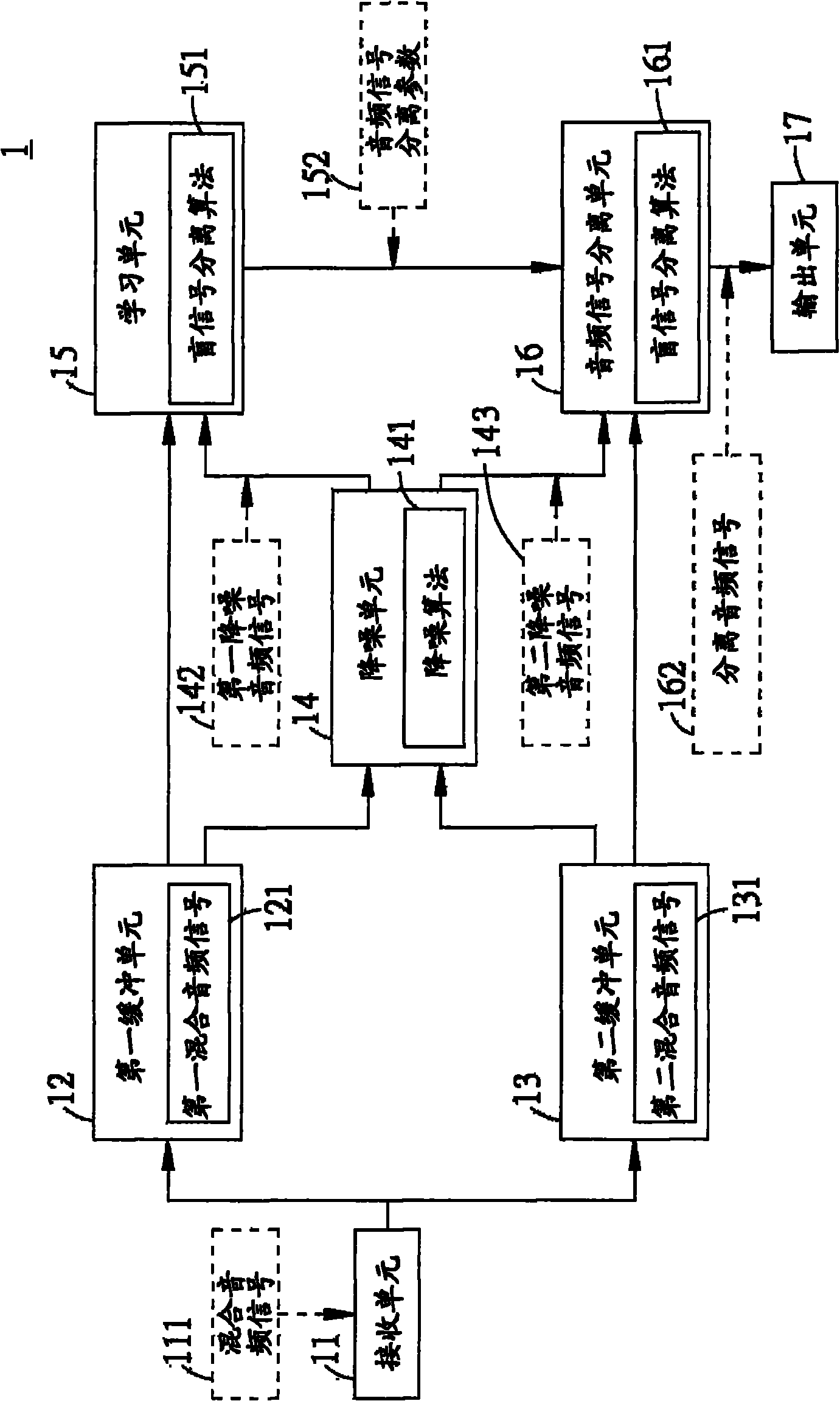
[0032] refer to figure 1 , figure 1 is a schematic diagram of the audio signal separation device of the present invention. In the figure, the audio signal separation device 1 includes a receiving unit 11 , a first buffer unit 12 , a second buffer unit 13 , a noise reduction unit 14 , a learning unit 15 , an audio signal separation unit 16 and an output unit 17 .
[0033] The receiving unit 11 is a microphone for receiving the mixed audio signal 111 . The mixed audio signal 111 may be audio signals from multiple signal sources, and since only one microphone is used to receive the mixed signal, no spatial aliasing effect will be generated.
[0034] The first buffer unit 12 is connected to the receiving unit 11 and stores the mixed audio signal 111 as a first mixed audio signal 121 . The second buffer unit 13 is connected to the receiving unit 11, and stores the mixed audio signal 111 as the second mixed audio signal 131. The buffer capacity of the second buffer unit 13 is less than the buffer capacity of the first buffer unit 12, so the first buffer unit 12 can The longer mixed audio signal 111 is stored, while the second buffer unit 13 stores the shorter mixed audio signal 111 .
[0035] The noise reduction unit 14 is connected to the first buffer unit 12 and the second buffer unit 13 to receive the first mixed audio signal 121 and the second mixed audio signal 131, and use the noise reduction algorithm 141 to generate the first noise reduced audio signal 142 and the second mixed audio signal respectively. 2. Reduce the noise of the audio signal 143 . The purpose of the noise reduction algorithm 141 is to suppress noise (noise reduction). The mixed audio signal 111 may also be processed in a voice-enhanced manner.
[0036] The learning unit 15 is connected to the first buffer unit 12 and the noise reduction unit 14 to receive the first mixed audio signal 121 and the first noise-reduced audio signal 142, and the learning unit 15 uses the blind signal separation algorithm 151 to pass the first mixed audio signal 121 and the first noise-reduced audio signal 142. The first noise-reduced audio signal 142 produces a learned result. When there are m sound sources (s), there are n mixed signals (x) received. When the signal characteristics are not known, using n received signals to separate m sound sources is the Blind Source Separation (BSS) algorithm. It can be expressed mathematically as follows: X n×1 =A n×m S m×1 , where A is a mixing matrix, which is affected by environmental factors. In practical applications, it can be assumed that the m sound sources are independent of each other, so the de-mixing matrix (de-mixing matrix) W≈A can be obtained by using the solo component analysis method -1 , and the separation signal Y is approximate to S, expressed by the following equation: Y m×1 =W m×n x n×1 ≈S. Therefore, it can be assumed that the de-mixing matrix (de-mixing matrix) W=A -1 , at this time, the obtained separation signal Y=S, and expressed by the following equation: Y m×1 =W m×n x n×1. Therefore, the learning unit 15 can generate an audio signal separation parameter 152 through a blind signal separation algorithm 151 , and the audio signal separation parameter 152 can be a matrix parameter or an anti-mixing matrix W.
[0037] The audio signal separation unit 16 is connected to the second buffer unit 13, the noise reduction unit 14 and the learning unit 15, so the audio signal separation unit 16 can receive the second mixed audio signal 131, the second noise reduction audio signal 143 and the audio signal separation parameter 152 to get the separation signal. When the audio signal separation unit 16 does not receive the audio signal separation parameter 152, it should use the preset (default) parameter or directly output without separation. The audio signal separating unit 16 can obtain a separated signal through the second mixed audio signal 131 and the second noise-reduced audio signal 143 . When the audio signal separation unit 161 receives the audio signal separation parameter 152, the audio signal separation unit 161 can obtain the anti-mixing matrix W through the learning unit 15, and operate with the mixed signal X to obtain the separation signal Y, that is, Y as described above m×1 =W m×n x n×1 , so the audio signal separation unit 16 can use the second mixed audio signal 131 , the second noise-reduced audio signal 143 and the audio signal separation parameter 152 to separate the mixed audio signal 111 .
[0038] The audio signal separation device 1 may further include an output unit 17 to output a separated audio signal 162 . Wherein, the separated audio signal 162 is an audio signal obtained after separating the mixed audio signal 111 . The present invention is by arranging two buffer units with different sizes, the buffer capacity of the second buffer unit 13 is less than the buffer capacity of the first buffer unit 12, so the audio signal separation unit 16 can process the second mixed audio signal 131 and the second reduced audio signal in real time. The noise signal 143 is extracted, and the separated audio signal 162 is output through the output unit 17 in real time. In addition, in order to make the learning time of the learning unit 15 longer, so as to obtain better learning results, the first buffer unit 12 with a larger buffer capacity can be set, so as to generate better audio signal separation parameters, so that the audio signal The separation unit 16 has better audio signal separation capability.
[0039] refer to figure 2 , figure 2 It is a flow chart of the steps of the operation method of the audio signal separation device of the present invention. Step S1, using the receiving unit to receive the mixed audio signal. When the receiving unit only uses one microphone, the microphone can receive the mixed audio signal, which can avoid the existing spatial aliasing effect generated by multiple microphones. In step S2, the receiving unit is connected through the first buffer unit, and the first buffer unit stores the mixed audio signal as a first mixed audio signal. Step S3, connect the receiving unit through the second buffer unit, the second buffer unit stores the mixed audio signal as the second mixed audio signal, and the buffer capacity of the second buffer unit is different from that of the first buffer unit. Step S4, connecting the first buffer unit and the second buffer unit through the noise reduction unit. Step S5, receiving the first mixed audio signal and the second mixed audio signal through the noise reduction unit. Step S6, using the noise reduction algorithm to make the noise reduction unit generate the first noise reduction audio signal and the second noise reduction audio signal respectively. Step S7, connecting the first buffer unit and the noise reduction unit through the learning unit. Step S8, through the blind signal separation algorithm, the learning unit uses the first mixed audio signal and the first noise-reduced audio signal to generate audio signal separation parameters. Step S9, using the audio signal separation unit to connect the noise reduction unit, the second buffer unit and the learning unit. In step S10, the audio signal separation unit uses the second mixed audio signal, the second noise-reduced audio signal and audio signal separation parameters to separate the mixed audio signal through a blind signal separation algorithm. Wherein, an output step S11 is further included, outputting the separated audio signal through the output unit.
[0040] refer to image 3 , image 3 It is a flow chart of steps in another embodiment of the operation method of the audio signal separation device of the present invention. Step S11, initial value setting. In this step, the buffer length of the first mixed audio signal of the first buffer unit and the buffer length of the second mixed audio signal of the second buffer unit can be set, and the learning time of the learning unit can be set. When the learning time is longer, better learning results can be obtained, resulting in better audio signal separation parameters.
[0041] Step S12, using the receiving unit to receive the mixed audio signal. Step S131, storing the audio signal through the first buffer unit. Step S132, storing the audio signal through the second buffer unit. Step S141, judging whether the first buffer unit is full. When it is judged that the first buffer unit is full, the first mixed audio signal is processed. If not, continue to store the audio signal through the first buffer unit.
[0042] Step S142, judging whether the storage of the second mixed audio signal is full. When it is judged that the second buffer unit is full, the second mixed audio signal is processed. If not, continue to store the audio signal through the second buffer unit. Step S151, performing noise suppression. In this step, the noise reduction unit may use a noise reduction algorithm to perform a noise reduction operation on the first mixed audio signal to generate a first noise reduction audio signal. Step S152, perform noise suppression. In this step, the noise reduction unit may use a noise reduction algorithm to perform a noise reduction operation on the second mixed audio signal to generate a second noise reduction audio signal.
[0043] Step S16, generating audio signal separation parameters. In this step, the learning unit performs a blind signal separation algorithm on the first mixed audio signal and the first noise reduction audio signal, thereby generating audio signal separation parameters, and transmitting the new audio signal separation parameters to the audio signal separation unit. Since the receiving unit is in the state of continuously receiving signals, and when the first buffer unit is full, processes such as noise suppression and generation of audio signal separation parameters are performed, so the audio signal separation parameters are in a state of continuous updating, so when performing each iterative process, A new audio signal separation parameter is generated.
[0044] Step S17, judging whether a new audio signal separation parameter is received. When the audio signal separation unit determines that a new audio signal separation parameter has been received, go to step S18 to update the audio signal separation parameter. And proceed to step S19 to separate the audio signal. Computing the updated audio signal separation parameters with the mixed signal to obtain the separated signal. When the audio signal separation unit judges that no audio signal separation parameter has been received, it directly proceeds to step S19 to separate the audio signal. Proceed to step S20 to determine whether to end. When the user desires to end the audio signal separation process, the audio signal separation device can be turned off, and the operation will end at this time. When the user continues to operate the audio signal separation device, return to step S131 or S132 to store the audio signal through the first buffer unit or the second buffer unit.
[0045] refer to Figure 4 , Figure 4 is the signal plot of the two signal sources. In the figure, the upper signal is a speech (speech) signal 41 , and the lower signal is a noise (noise) signal 42 . refer to Figure 5 , Figure 5 It uses two microphones to record the signal diagrams of two signal sources respectively. Since the distance between the two microphones in this diagram is only 1 cm, the recorded signal diagrams of the two microphones are similar. refer to Image 6 , Image 6 is a known signal diagram of applying a Wiener filter to a microphone recording signal (as shown in Figure 5). By comparison Figure 4 , it can be found that the filter has filtered out the noise 42, but also lost part of the speech 41 segment.
[0046] refer to Figure 7 , Figure 7 is an existing signal diagram of a microphone recording signal analyzed using the Independent Component Analysis (ICA) method. Wherein, when two signal sources are recorded through two microphones, the two signal sources are voice signal 41 and noise signal 42 . When the ICA method is used, two separate signals can be generated, one is a speech signal and the other is a noise signal. The signal represented in this figure is part of the speech signal. Due to the spatial aliasing effect produced by recording with two microphones, the noise suppression effect of directly using ICA is not significant. By means of ICA, both the noise 42 and the voice signal 41 are included in the signal, but the noise 42 is too much to obtain a better voice signal 41 .
[0047] refer to Figure 8 , Figure 8 is a signal diagram of the audio signal separation device to which the present invention is applied. By comparison Figure 4 , it can be found that the original speech signal 41 is in this signal diagram, and the noise 42 is effectively suppressed. Additionally, by comparing Figure 7 , the effect of noise suppression is better than that of ICA, and the hearing-impaired can use this device to get better speech signals.
[0048] The foregoing is for purposes of illustration only and not limitation. Any equivalent modifications or changes made without departing from the spirit and scope of the present invention shall be included in the scope of the appended claims.

PUM

no PUM

Description & Claims & Application Information

We can also present the details of the Description, Claims and Application information to help users get a comprehensive understanding of the technical details of the patent, such as background art, summary of invention, brief description of drawings, description of embodiments, and other original content. On the other hand, users can also determine the specific scope of protection of the technology through the list of claims; as well as understand the changes in the life cycle of the technology with the presentation of the patent timeline. Login to view more.

Similar technology patents

Multi-wavelength Brillouin optical time domain analyzer

InactiveCN103115632AIncrease total optical powerImprove signal-to-noise ratioSpecial purpose recording/indication apparatusOptical pathSignal-to-noise ratio (imaging)
Owner:NANJING UNIVERSTIY SUZHOU HIGH TECH INST +1

Classification and recommendation of technical efficacy words

  • Improve signal-to-noise ratio

Magnetic tape, its cleaning method, and optical servotrack forming/cleaning apparatus

InactiveUS7803471B1Improve signal-to-noise ratioDecreasing rate of fluctuationMagnetic materials for record carriersReconditioning/cleaning record carriersReflectivityMaximum rate
Owner:FUJIFILM CORP

System for generating thermographic images using thermographic signal reconstruction

ActiveUS20050008215A1Reduce size and complexityImprove signal-to-noise ratioCharacter and pattern recognitionMaterial flaws investigationSignal reconstructionThermographic imaging
Owner:THERMAL WAVE IMAGING

Hyper-spectral imaging methods and devices

InactiveUS20050270528A1Improve signal to noise ratioSmall bandwidthRadiation pyrometrySpectrum generation using diffraction elementsSpectral imagingLight spectrum
Owner:PLAIN SIGHT SYST
Why Eureka
Try Eureka