Self-lubricating and self-cooling dry cutter and manufacturing method thereof

A self-cooling, dry cutting technology, applied in lathe tools, turning equipment, manufacturing tools, etc., can solve the problems of increased cutting temperature, increased friction, and decreased tool life

Inactive Publication Date: 2011-04-06
SHANDONG UNIV
View PDF6 Cites 23 Cited by
  • Summary
  • Abstract
  • Description
  • Claims
  • Application Information

AI Technical Summary

Problems solved by technology

However, during dry cutting, due to the lack of lubrication and cooling effects of cutting fluid, the friction between the tool and the workpiece is intensified,

Method used


Image

  • Self-lubricating and self-cooling dry cutter and manufacturing method thereof
  • Self-lubricating and self-cooling dry cutter and manufacturing method thereof
  • Self-lubricating and self-cooling dry cutter and manufacturing method thereof

Examples


Embodiment 1

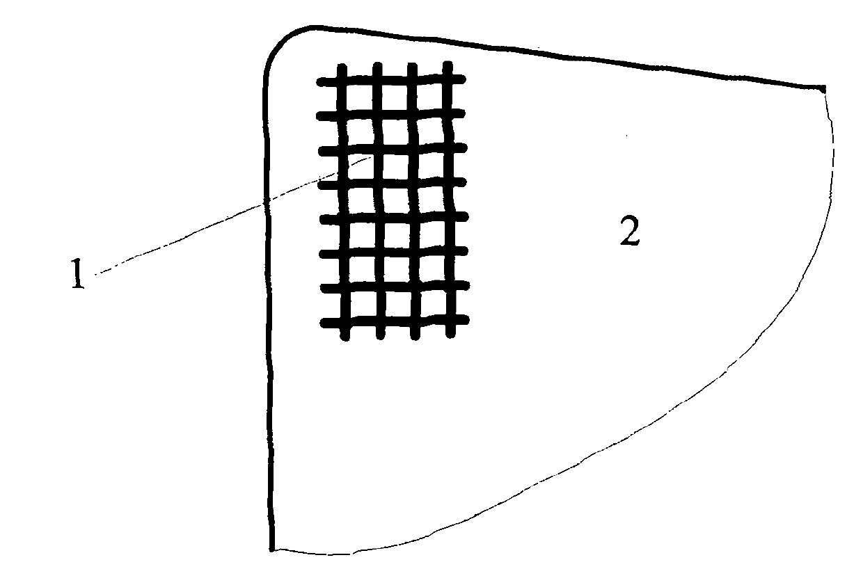
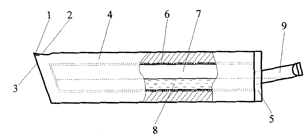
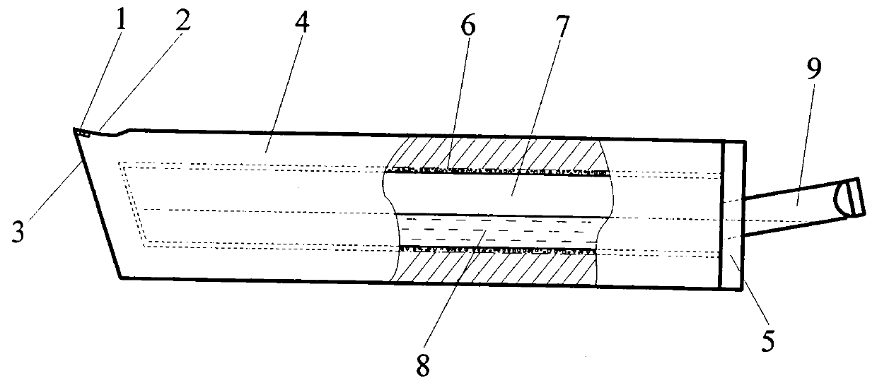
[0016] A self-lubricating and self-cooling dry cutting tool. The material of the tool is high-speed steel. There are multiple micro-friction-reducing grooves 1 filled with solid lubricant in the chip contact area of ​​the rake face 2 of the tool. Self-circulating cooling chamber. Its preparation method is as follows:

[0017] 1. The inner cavity 7 is processed forward from the rear end of the cutter body 4 by using electric discharge machining technology. The cavity 7 is a rectangle with a cross-section of 18×18mm centered along the cutter body section, ensuring that the upper, lower, left, and right wall thicknesses of the cutter cavity are uniform. 6mm, the front end of the cavity 7 is processed to a place close to the front end of the cutter body 4, ensuring that the wall thickness of the front end of the cavity is equivalent to the wall thickness of the side;

[0018] 2. Take a copper plate with a thickness of 5mm and a shape and size of 30×30mm as the rear end cover 5 of...

Embodiment 2

[0024] A self-lubricating and self-cooling dry cutting tool as described in Example 1, the difference is that the working medium of the cooling chamber, the size of the anti-friction groove, and the type of lubricant are different, and its preparation method is as follows:

[0025] 1. The inner cavity 7 is processed forward from the rear end of the cutter body 4 by using electric discharge machining technology. The cavity 7 is a rectangle with a cross-section of 15×15mm centered along the cutter body section, ensuring that the upper, lower, left, and right wall thicknesses of the cutter cavity are uniform. 5mm, the front end of the cavity 7 is processed to a place close to the front end of the cutter body 4, ensuring that the wall thickness of the front end of the cavity is equivalent to the wall thickness of the side;

[0026] 2. Take a copper plate with a thickness of 5mm and a shape and size of 25×25mm as the rear end cover 5 of the cooling chamber of the cutter body, and us...


PUM


Abstract

The invention provides a manufacturing method of self-lubricating and self-cooling dry cutter, belonging to the technical field of mechanical cutter manufacturing. A cutter-scrap contact zone on a front cutter face of the cutter is provided with a plurality of miniature antifriction slots filled with solid lubricants, and the solid lubricants in the antifriction slots are coated on the front cutter face of the cutter in a towing way by the jointed action of cutting heat and scrap extrusion to form a continuous solid lubricating film so that the self-lubricating function of the cutter is realized; and a self-circulation cooling cavity is arranged in a cutter body, during cutting processing, a liquid medium in the cooling cavity absorbs heat transferred from the cutting part of the cutter so that the rapid heat radiation and cooling of the cutting part of the cutter can be effectively enhanced, thereby the self-cooling function of the cutter is realized. The cutter can reduce the frication of the cutting part with a workpiece and also lower the cutting temperature so that the friction of the cutter is reduced, the processing quality of the workpiece and the durability of the cutter are improved, and the cutter can be widely applied to dry cutting and cutting of materials difficult to process and realizes clean production.

Description

1. Technical field [0001] The invention belongs to the technical field of mechanical cutting tool manufacturing, in particular to a dry cutting tool with dual functions of self-lubricating and self-cooling and a preparation method thereof. 2. Background technology [0002] The main function of cutting fluid is to improve the friction and lubrication state of the cutting process, reduce the cutting temperature, thereby prolonging the life of the tool and improving the surface quality of the workpiece. However, with the increase in the amount of cutting fluid, its negative impact is also increasing. The manufacture, use and discharge of cutting fluid consume a lot of energy and resources, which increases the manufacturing cost of the product, and the cutting fluid will cause serious damage to the environment. pollution and damage to workers' health. The solution to this problem is to use dry machining technology. However, during dry cutting, due to the lack of lubrication an...

Claims


Application Information

Patent Timeline
IPC IPC(8): B23B27/00B23B27/10B23P15/30
Inventor 邓建新吴泽亓婷
Owner SHANDONG UNIV
Why Eureka
Try Eureka